Material pneumatic conveying device cleaning device

A pneumatic conveying and cleaning device technology, applied in the direction of cleaning hollow objects, cleaning methods and utensils, chemical instruments and methods, etc., can solve problems such as adsorption of conveying pipes and affecting the use of conveying pipes

Inactive Publication Date: 2018-11-30
WUHU NEW UNIVERSAL ENVIRONMENTAL SCI TECH
View PDF5 Cites 3 Cited by
  • Summary
  • Abstract
  • Description
  • Claims
  • Application Information

AI Technical Summary

Problems solved by technology

[0005] Aiming at the deficiencies of the prior art, the present invention provides a cleaning device for material pneumatic conveyi

Method used


Image

  • Material pneumatic conveying device cleaning device
  • Material pneumatic conveying device cleaning device

Examples


Embodiment Construction

[0021] The following will clearly and completely describe the technical solutions in the embodiments of the present invention with reference to the accompanying drawings in the embodiments of the present invention. Obviously, the described embodiments are only some, not all, embodiments of the present invention. Based on the embodiments of the present invention, all other embodiments obtained by persons of ordinary skill in the art without making creative efforts belong to the protection scope of the present invention.

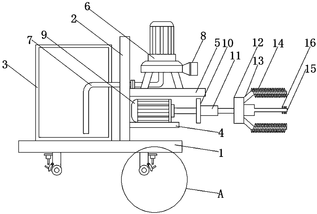
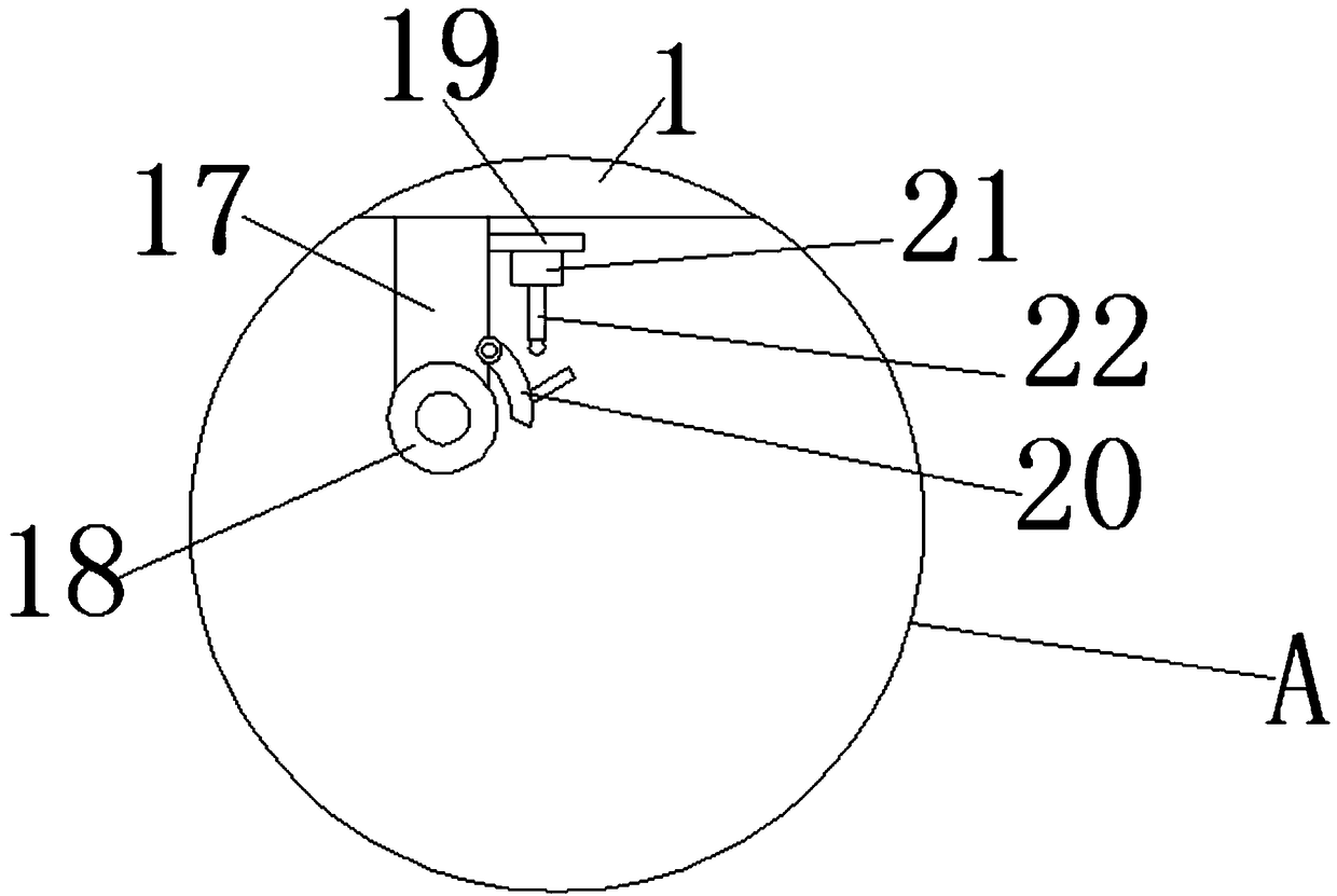
[0022] Such as Figure 1-2 As shown, the embodiment of the present invention provides a cleaning device for pneumatic conveying equipment, including a base 1, a mounting plate 2 and a water tank 3 are fixedly mounted on the top of the base 1, and a motor bracket 4 and a water pump bracket are fixedly mounted on the right side of the mounting plate 2 5. The water pump bracket 5 is located above the motor bracket 4. The water pump 6 is fixedly installed on the t...


PUM


Abstract

The invention provides a material pneumatic conveying device cleaning device, relating to the technical field of cleaning devices. The material pneumatic conveying device cleaning device includes a base. A mounting plate and a water tank are fixedly mounted at the top of the base, a motor bracket and a water pump bracket are fixedly mounted on the right side of the mounting plate, a water pump isfixedly mounted at the top of the water pump bracket, a water inlet of the water pump is movably connected with a water pipe, a spray head is fixedly mounted on a water outlet of the water pump, and amotor is fixedly mounted at the top of the motor bracket. According to the material pneumatic conveying device cleaning device, through the cooperation of the motor, an electric telescopic rod, a brush rod, a hairbrush, a detergent tank and a pipe opening, the motor is started, a connecting plate and the brush rod that are fixedly mounted at the output end of the motor start to rotate, the hairbrush carries out friction on the inner wall of an output pipe, a detergent in a cleaning machine box is thrown out of the pipe opening, and thus a material conveying pipe can be sufficiently washed.

Description

technical field [0001] The invention relates to the technical field of cleaning devices, in particular to a cleaning device for material pneumatic conveying equipment. Background technique [0002] Pneumatic conveying equipment has a good dust-proof effect, is easy to realize mechanization and automation, can reduce labor intensity and save manpower; in the process of conveying, it can carry out various technological operations at the same time, such as mixing, crushing, sorting, drying and cooling. [0003] Pneumatic conveying equipment generally consists of a receiver (such as a throat, a suction nozzle, a transmitter, etc.), a conveying pipe, an air pipe, a separator (commonly used in two types: volumetric and cyclone), and an air lock (commonly used in a flipper). Plate type and rotary type, which can be used as feeder or unloader), dust collector and fan (such as centrifugal fan, Roots blower, water ring vacuum pump, air compressor, etc.) and other equipment and compone...

Claims


Application Information

Patent Timeline
IPC IPC(8): B08B9/027B08B9/032
CPCB08B9/027B08B9/0321
Inventor 邢健阮亮
Owner WUHU NEW UNIVERSAL ENVIRONMENTAL SCI TECH
Why Eureka
Try Eureka