
High-efficient scrap-removal pentahedron machining center

A machining center and pentahedron technology, applied in the direction of metal processing equipment, metal processing machinery parts, manufacturing tools, etc., can solve the problems of time-consuming, labor-intensive, speeding up the processing speed of CNC bed body, troublesome chip removal, etc., to achieve convenient use, structure Compact and easy chip removal

Inactive Publication Date: 2018-11-30
深圳市钜人数控设备有限公司
View PDF7 Cites 10 Cited by
  • Summary
  • Abstract
  • Description
  • Claims
  • Application Information

AI Technical Summary

Problems solved by technology

[0002] The pentahedron machining center refers to the use of a compound milling head, that is to say, its milling head can be removed, installed with a compound milling head, and the milling head can turn the angle. Except for the surface of the worktable, it is not easy to process, and the others are easy to process. , mostly refers to the gantry machining center. The pentahedron machining center is an improvement to the ordinary CNC machining bed. It can process five different surfaces through one clamping, which greatly speeds up the processing speed of the CNC bed without changing the surface. During tool change processing and machine tool processing, the processed workpiece and workbench will be covered with iron chips, which will affect the processing, and the subsequent chip removal is troublesome, time-consuming and labor-intensive. Therefore, we propose a highly efficient chip removal pentahedral machining center

Method used


Image

  • High-efficient scrap-removal pentahedron machining center
  • High-efficient scrap-removal pentahedron machining center
  • High-efficient scrap-removal pentahedron machining center

Examples


Embodiment Construction

[0019] The following will clearly and completely describe the technical solutions in the embodiments of the present invention with reference to the accompanying drawings in the embodiments of the present invention. Obviously, the described embodiments are only some, not all, embodiments of the present invention. Based on the embodiments of the present invention, all other embodiments obtained by persons of ordinary skill in the art without making creative efforts belong to the protection scope of the present invention.

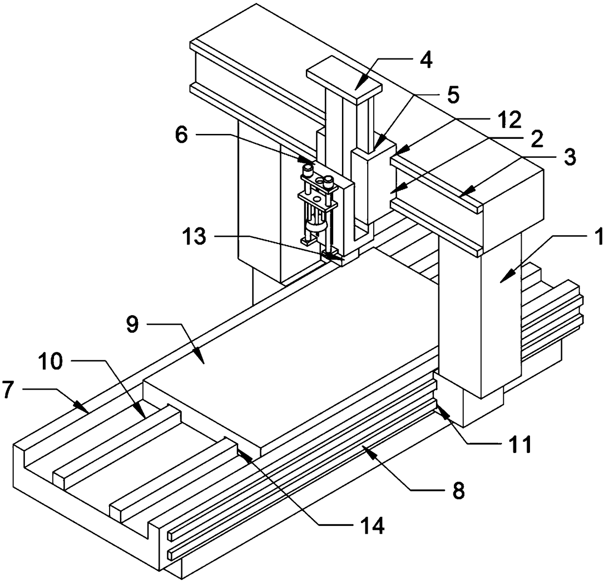
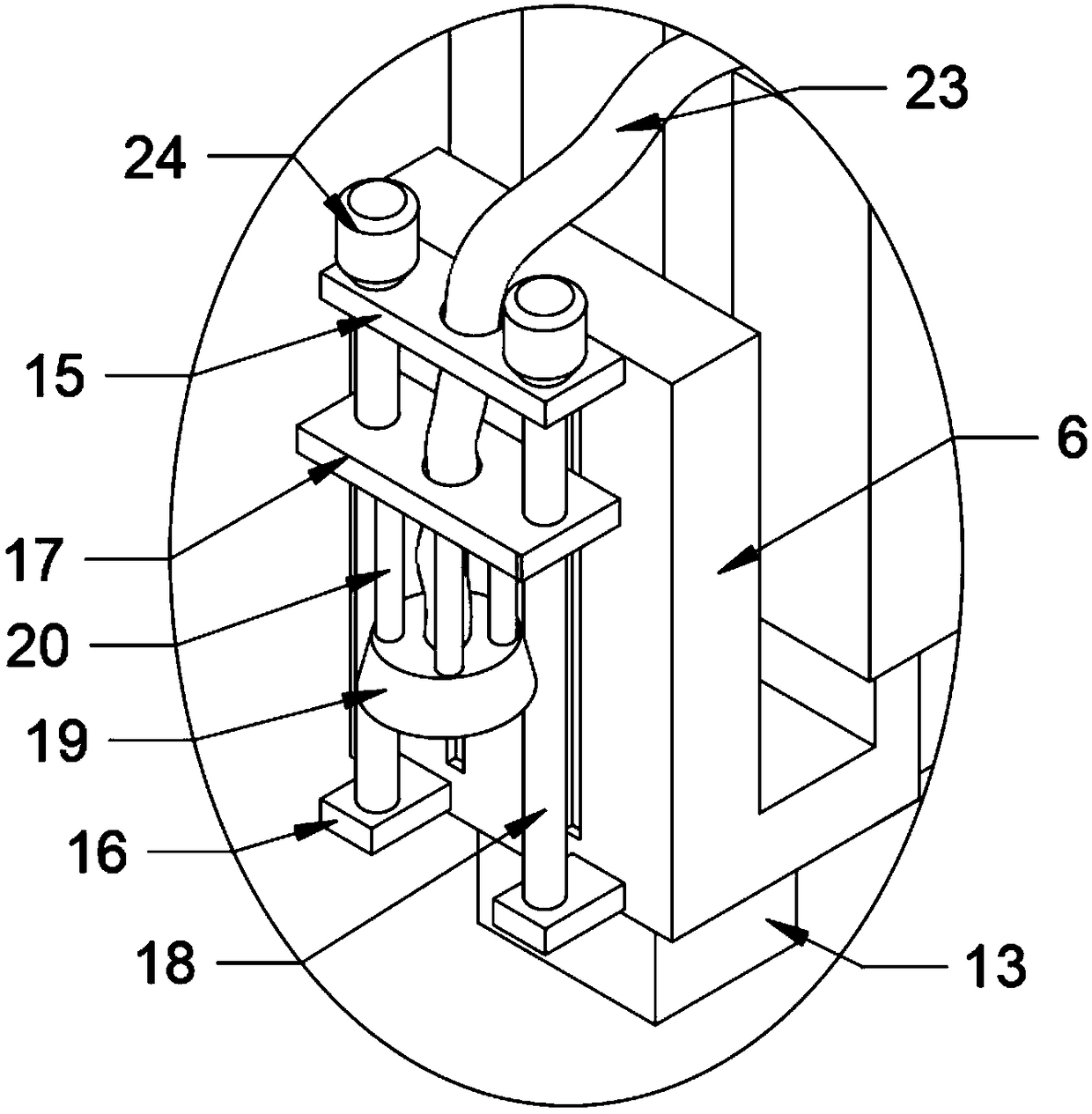
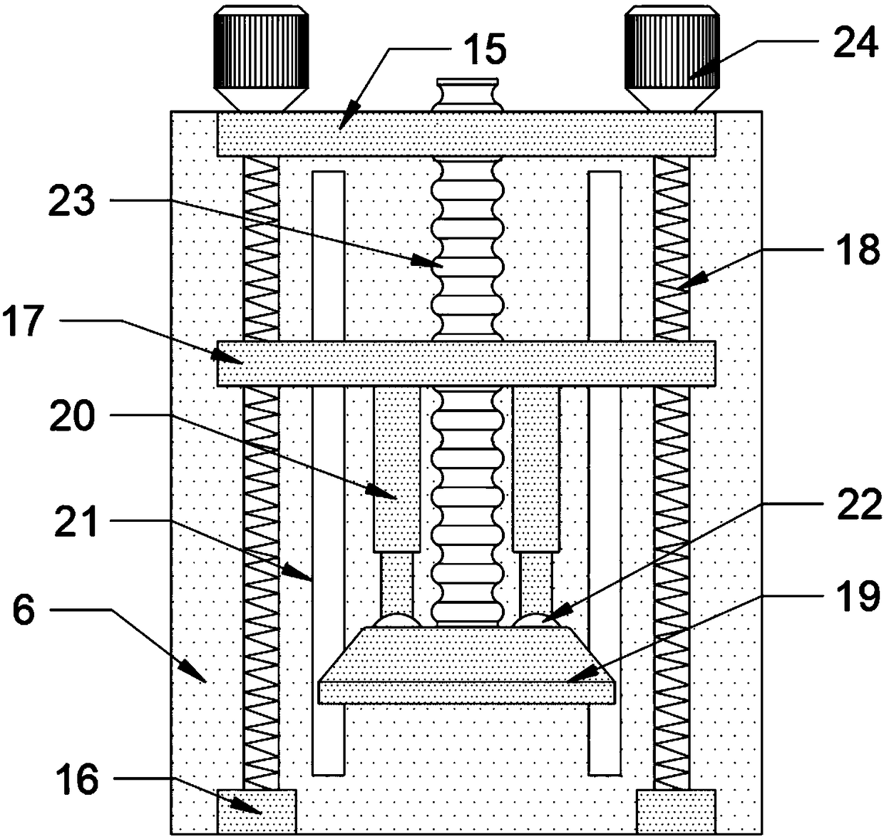
[0020] see Figure 1-6 , the present invention provides a technical solution: a high-efficiency chip removal pentahedron machining center, including a gantry 1, a horizontal moving block 2, a horizontal guide rail 3, a vertical moving block 4, a card slot 5, a mounting block 6, and a base 7 , longitudinal guide rail 8, processing plate 9, sliding guide rail 10, longitudinal guide groove 11, transverse guide groove 12, pentahedron processing block 13, sliding g...


PUM


Abstract

The invention discloses a high-efficient scrap-removal pentahedron machining center. The high-efficient scrap-removal pentahedron machining center comprises a portal frame, a transverse moving block,transverse guiding rails, a vertical moving block, a clamping slot, a mounting block, a base, longitudinal guide rails, a processing plate, sliding guide rails, longitudinal guide slots, transverse guide slots, a pentahedron processing block, sliding guide slots, an upper mounting plate, a lower mounting plate, a movable plate, a lifting lead screw, a scrap removal shell, electromagnetic telescopic rods, sliding slots, universal bearings, a telescopic guide pipe, a rotating motor, threaded holes and sliding rails, wherein the longitudinal guide rails are fixed to the two sides of the base; theportal frame is arranged above the base; the corresponding sides, close to the base, of the two-sided bottom ends of the portal frame are provided with the longitudinal guide slots matched with the longitudinal guide rails; a scrap-removal structure of the pentahedron machining center can be comprehensively moved along with a cutter fixing device, so that the use of an adjusting driving machine of the scrap-removal device is reduced and scraps are convenient to remove, and meanwhile, through cooperation application of the electromagnetic telescopic rods with different telescopic lengths, a scrap-removal shell and different inclined surfaces can be placed in parallel, so that the scrap-removal precision is improved.

Description

technical field [0001] The invention relates to the technical field of pentahedron machining centers, in particular to a highly efficient chip-removing pentahedron machining center. Background technique [0002] The pentahedron machining center refers to the use of a compound milling head, that is to say, its milling head can be removed, installed with a compound milling head, and the milling head can turn the angle. Except for the surface of the worktable, it is not easy to process, and the others are easy to process. , mostly refers to the gantry machining center. The pentahedron machining center is an improvement on the ordinary CNC machining bed. It can process five different surfaces through one clamping, which greatly speeds up the machining speed of the CNC bed without changing the surface. During tool change processing and machine tool processing, the processed workpiece and workbench will be covered with iron chips, which will affect the processing, and the follow-u...

Claims


Application Information

Patent Timeline
IPC IPC(8): B23C1/12B23Q11/00
CPCB23C1/12B23Q11/0042
Inventor 黄小四赖国平江喜允艾先亮
Owner 深圳市钜人数控设备有限公司
Learn More