A multi-row chain chain hoist

A chain hoist and wall panel technology, which is applied in hoisting devices and clockwork mechanisms, etc., can solve the problems of large overall volume, increased material cost, and large hook spacing, and achieve the effect of saving space and reducing the hook spacing

Active Publication Date: 2019-11-05
CHONGQING VITAL ELEVATORING EQUIP
View PDF4 Cites 2 Cited by
  • Summary
  • Abstract
  • Description
  • Claims
  • Application Information

AI Technical Summary

Problems solved by technology

There are two bifurcated extensions, one of which is connected to the main body mechanism with a gear shaft, and the other extension is connected to the driven wheel mechanism with a driven wheel and a driven shaft, because all the force is distributed to the On the two extensions, the two extensions need to bear greater gravity. Therefore, the weight of the upper hook and its extension is usually designed to be larger to withstand greater weight. At the same time, due to structural reasons, the distance between the hooks is also relatively large. Large, the overall volume is too large, the cost of materials increases, the weight of the machine body is heavy, and the technical difficulty of connecting the hook frame to the hook frame increases

Method used


Image

  • A multi-row chain chain hoist
  • A multi-row chain chain hoist
  • A multi-row chain chain hoist

Examples


Embodiment 1

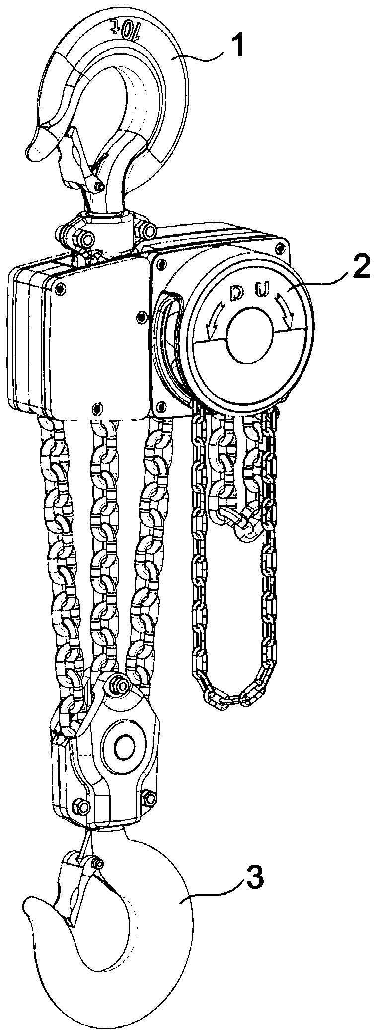
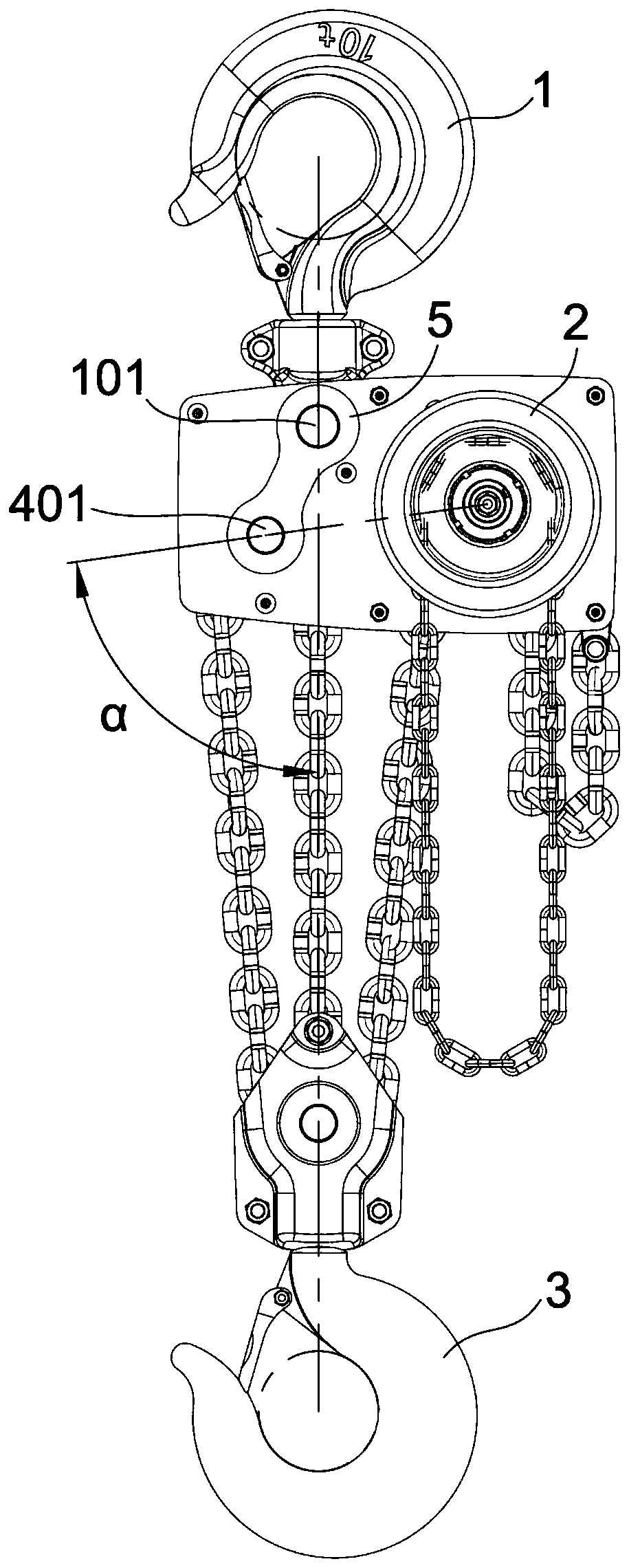
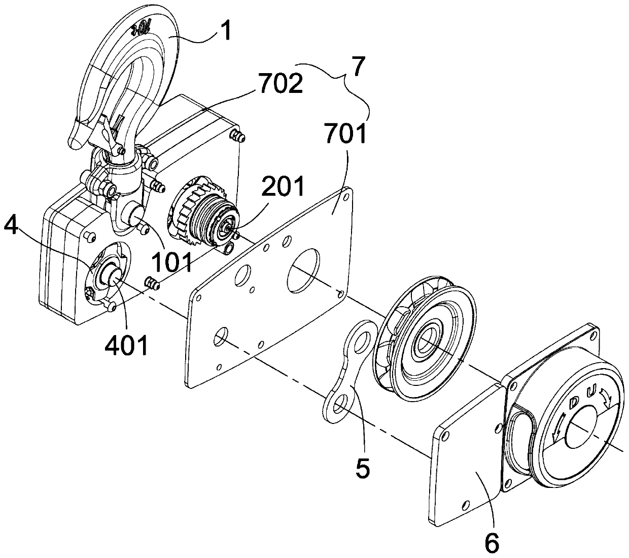
[0021] refer to Figure 1-3 , the three-chain chain hoist of the present invention includes an upper hook 1, a lower hook 3, a wall panel assembly 7, a main body mechanism 2 and a driven wheel mechanism 4, the upper hook 1 includes an upper hook shaft 101, and the main body mechanism 2 includes a hand chain wheel, Assemblies such as hand chain, ratchet, gear shaft 201, and driven wheel mechanism 4 then comprises driven wheel and driven shaft 401, and in the present embodiment, wallboard assembly 7 comprises first wallboard 701 and second wallboard 702, uses It is used to support the gear shaft 201 of the main body mechanism 2 , the upper hook shaft 101 of the upper hook 1 and the driven shaft 401 of the driven wheel mechanism 4 .

[0022] Both the main body mechanism 2 and the driven wheel mechanism 4 are arranged on the wall panel assembly 7, and there is a first axis connecting line between the axis center of the main body mechanism 2 and the axis center of the driven wheel ...

Embodiment 2

[0027] refer to Figure 4 , The difference between the four-chain chain block and the three-chain chain block in this embodiment is that the lifting chain is a four-row chain. The four-chain chain block also has an upper hook 1, a lower hook 3, a wall panel assembly 7, a main body mechanism 2 and a driven wheel mechanism 4. The main body mechanism 2 is arranged on the wall panel assembly 7, and the driven wheel mechanism 4 is arranged on the wall panel assembly 7. On the derivative structure of the wall panel assembly 7 where the main body mechanism 2 is located, so that the main body mechanism 2 and the driven wheel mechanism 4 are fixed on the wall panel assembly 7 in a horizontally side-by-side manner, which can reduce the width dimension and the vertical dimension, Therefore, the volume of the entire chain hoist is reduced, and the space layout is more compact.

[0028] Referring to the three-chain chain hoist and the four-chain chain hoist, other multi-row chain chain ho...


PUM


Abstract

The invention discloses a chain hoist with a plurality of rows of chains. The chain hoist comprises an upper hook, a lower hook, a wall plate assembly, a main body mechanism and a driven wheel mechanism and is characterized in that the main body mechanism and the driven wheel mechanism are arranged on the wall plate assembly, a first axis connecting line is arranged between the axis of the main body mechanism and the axis of the driven wheel mechanism, a second axis connecting line is arranged between a hook body of upper hook and a hook body of the lower hook, and the inclined angle alpha between the first axis connecting line and the second axis connecting line ranges from 70 degrees to 90 degrees; the wall plate assembly comprises at least two wall plates; a driving lifting wheel of themain body mechanism and a driven moving wheel of the driven wheel mechanism are supported by the same wall plate. The chain hoist with the plurality of rows of chains is compact in space structure, small in size and low in weight.

Description

technical field [0001] The invention belongs to the technical field of hoisting and traction devices, and in particular relates to a multi-row chain chain hoist. Background technique [0002] At present, for multi-row chain chain hoists, the upper hook assembly includes a driven wheel structure, which is usually used in the following structural form: the upper hook covers the driven wheel assembly and is separated from the body, and is not on the same load-bearing body. There are two bifurcated extensions, one of which is connected to the main body mechanism with a gear shaft, and the other extension is connected to the driven wheel mechanism with a driven wheel and a driven shaft, because all the force is distributed to the On the two extensions, the two extensions need to bear greater gravity. Therefore, the weight of the upper hook and its extension is usually designed to be larger to withstand greater weight. At the same time, due to structural reasons, the distance betw...

Claims


Application Information

Patent Timeline
Patent Type & Authority Patents(China)
IPC IPC(8): B66D1/04B66D1/14
CPCB66D1/04B66D1/14
Inventor 符想念王春翔严帅杰刘洋
Owner CHONGQING VITAL ELEVATORING EQUIP
Why Eureka
Try Eureka