
Concrete pouring workbench for house construction

A technology for concrete and workbench, applied in construction, building structure, processing of building materials, etc., can solve the problems of inconvenient pouring, increase labor force, etc., and achieve the effect of easy discharging, reducing impurities, and easy pouring

Active Publication Date: 2020-09-04
浙江中乐建设有限公司
View PDF6 Cites 0 Cited by
  • Summary
  • Abstract
  • Description
  • Claims
  • Application Information

AI Technical Summary

Problems solved by technology

[0004] However, when the house construction concrete pouring workbench is in use, it is necessary to manually hold the pouring pipes for pouring, which increases the labor force and is not convenient for pouring

Method used


Image

  • Concrete pouring workbench for house construction
  • Concrete pouring workbench for house construction
  • Concrete pouring workbench for house construction

Examples


Embodiment Construction

[0042] The present invention will be described in further detail below in conjunction with the accompanying drawings. Wherein the same components are denoted by the same reference numerals. It should be noted that the words "front", "rear", "left", "right", "upper" and "lower" used in the following description refer to the directions in the drawings, and the words "bottom" and "top "Face", "inner" and "outer" refer to directions toward or away from, respectively, the geometric center of a particular component.

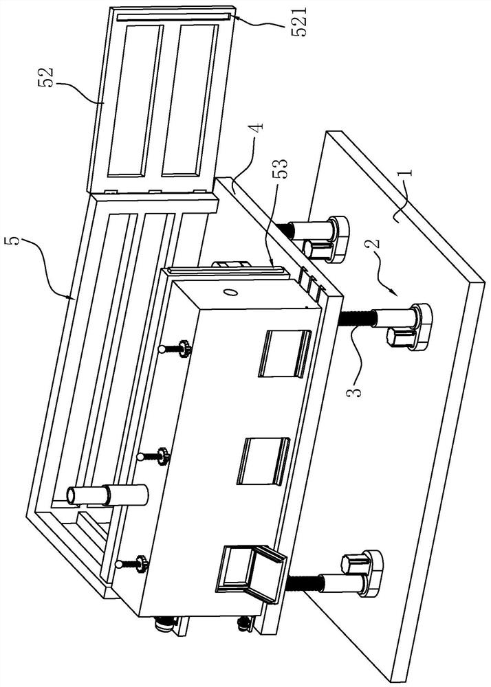
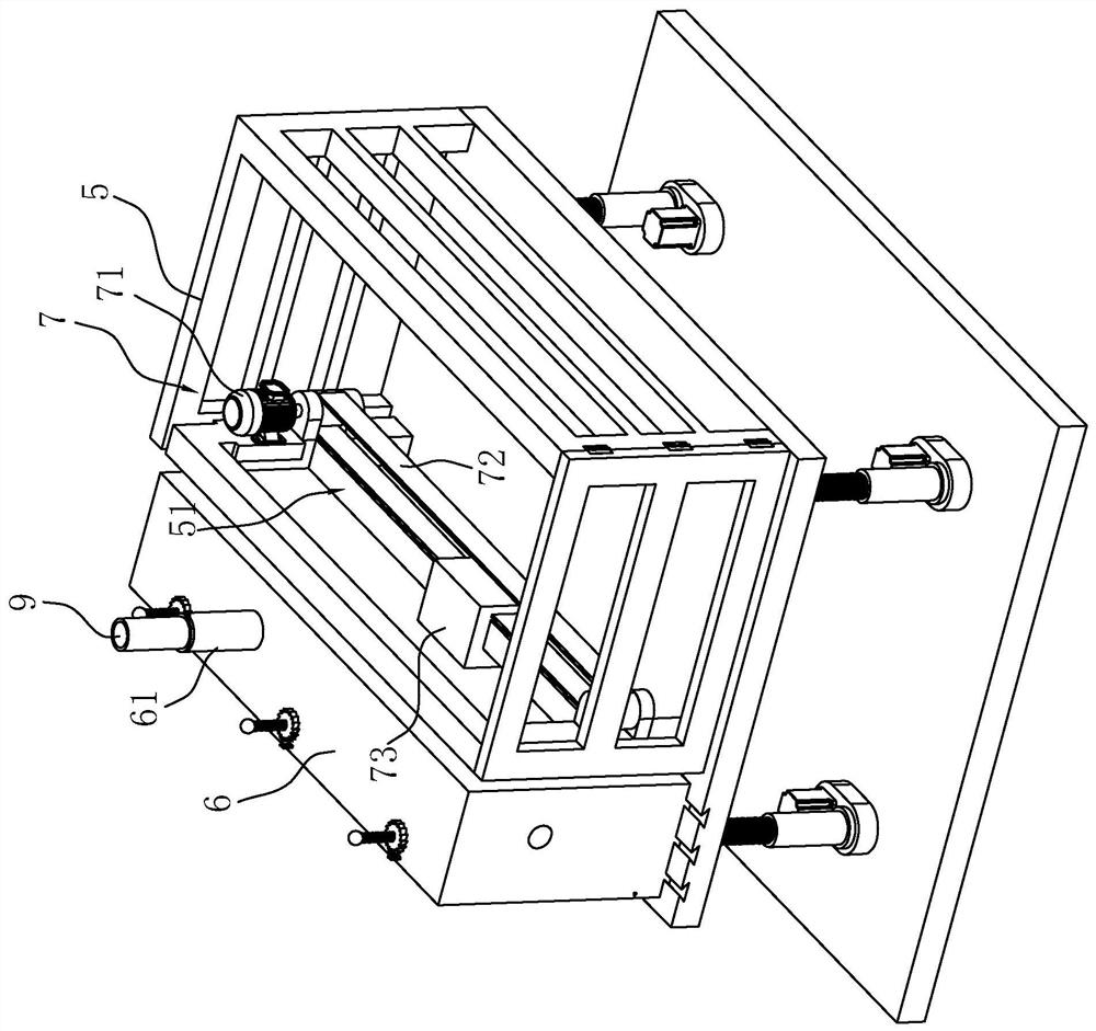
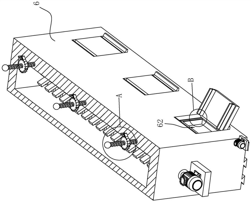
[0043] A concrete pouring platform for house construction, such as figure 1 and figure 2 As shown, it includes a base 1, a lifting assembly fixed on the top of the base 1, and a connecting frame 4 arranged on the lifting assembly; the lifting assembly includes electric push rods 2, and electric push rods 2 are arranged at the four corners of the bottom end of the connecting frame 4, The electric push rod 2 includes a screw rod 3 , and the top end of the screw rod 3...


PUM


Abstract

The invention discloses a house construction concrete pouring workbench, and relates to the field of house construction concrete pouring. The workbench comprises a base, a connecting frame verticallyconnected with the base in the sliding mode and a lifting assembly arranged at the top end of the base and driving the connecting frame to slide. One side of the top end of the connecting frame is horizontally and fixedly connected with a guiding rod, and the connecting frame is provided with a containing box in sliding connection with the guiding rod. The guiding rod is provided with a driving member for driving the containing box to slide. The top end of the containing box is fixedly connected with an insertion pipe in insertion connection with a pouring pipe. One side of the containing boxaway from the guiding rod is provided with a plurality of discharging ports, the bottom ends of the discharging ports are hinged with a guiding plate, and the guiding plate can be rotated to close thedischarging ports. During pouring, the pouring pipe is inserted into the insertion pipe, so that concrete enters the containing box. The concrete in the containing box is discharged from the discharging ports and poured into the position to be poured through the guiding plate. The different positions can be poured conveniently by means of sliding of the containing box in the connection.

Description

technical field [0001] The invention relates to the field of concrete pouring for house construction, and more specifically, to a concrete pouring workbench for house construction. Background technique [0002] Housing construction refers to the houses or places where people carry out production, living, living or other activities, such as industrial buildings, civil buildings, agricultural buildings, etc.; housing construction concrete pouring workbench is an auxiliary device for overall pouring in housing construction work . [0003] For the prior art, please refer to the invention patent application with application publication number CN107476576A. This patent application discloses a concrete pouring workbench for house construction, which includes a beam with a rectangular cross section and a fixed bracket. The lower surface of the fixed bracket is welded with telescopic legs. The end is slidingly connected with a cylinder, the lower end of the cylinder is fixed with a ...

Claims


Application Information

Patent Timeline
Patent Type & Authority Patents(China)
IPC IPC(8): E04G21/04
CPCE04G21/04E04G21/0427
Inventor 吴敏敏王志海陈育翰吴成风曹雷剑
Owner 浙江中乐建设有限公司
Learn More