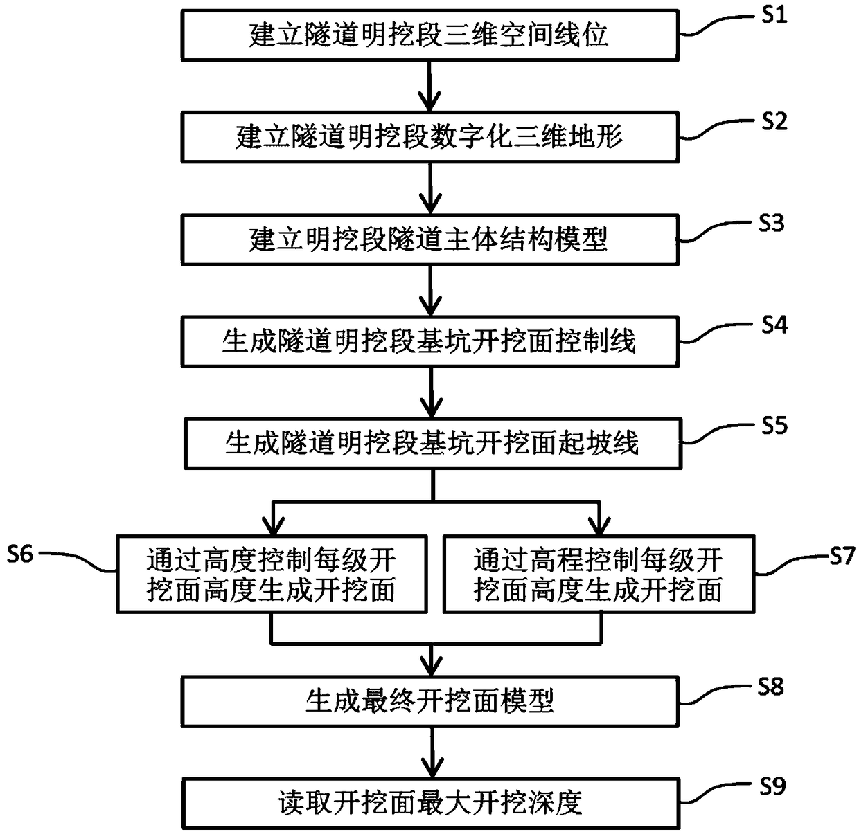
[0036] The specific technical solutions of the present invention will be described with reference to the drawings. by figure 1 As shown in the flow chart, the steps of the BIM-based open-cut section foundation pit excavation surface design method of the present invention include: establishing the three-dimensional space line position of the open-cut section of the tunnel, establishing the digital three-dimensional terrain of the open-cut section of the tunnel, and establishing the open-cut section The main structure model of the tunnel section, the generation of the control line of the excavation surface of the excavation section of the tunnel, the generation of the slope line of the excavation surface of the open section of the tunnel, the generation of the excavation surface through the height control of each level of the excavation surface, and the elevation control Each level of excavation surface height generates an excavation surface, generates a final brush slope model, and reads the maximum excavation depth of the excavation surface.
[0037] S1. Establish the three-dimensional space line position of the open-cut section of the tunnel
[0038] Relying on the level and vertical section of the route, the three-dimensional space curve of the route is generated in a three-dimensional environment.
[0039] S2. Establish a digital 3D terrain for the open-cut section of the tunnel
[0040] Relying on the measured pile number elevation data on the ground, a three-dimensional terrain surface is generated in a three-dimensional environment.
[0041] S3. Establish the main structure model of the open-cut section of the tunnel
[0042] Relying on the three-dimensional space line position, the tunnel structure model and the structure model of the cavern are established as the basis for designing the excavation boundary of the bottom surface of the open-cut foundation pit.
[0043] S4. Generate the control line of the excavation surface of the excavation section of the tunnel
[0044] Relying on the tunnel structure model and the cavern structure model, the boundary control line of the excavation surface of the bottom of the foundation pit is extracted, and the slope line of the excavation surface is generated based on this control line.
[0045] S5. Generate the slope line of the excavation surface of the excavated section of the tunnel
[0046] Offset the control line of the excavation surface of the open excavation section of the tunnel in S4 in the horizontal or vertical direction perpendicular to the line according to the actual required size of the excavation of the bottom of the foundation pit to obtain the starting line of the excavation surface ;
[0047] The process of generating the slope line (S5) of the excavation surface of the open-cut section of the tunnel is firstly to generate the control line of the excavation surface in the open-cut section of the tunnel (S4) within a certain error range. Curvature calculation is continuous, the calculated curve is named C1, and the curve C1 is projected on the horizontal plane along the vertical direction. This projection line is named C2, starting from the end point of C2, on the horizontal plane perpendicular to the direction of C2 with the required horizontal deviation Shift the length to generate a line segment. This line segment is named C3. C3 is scanned along C2 to form a plane. The outer line of the extracted sweeping surface is the line after the horizontal offset of C2. The extracted line is named C4. The vertical offset distance is stretched into a plane, and the top line of the extracted stretched surface is the line after C1 is offset vertically. This extracted line is named C5, with the endpoint of C5 as the starting point, perpendicular to C5 on the horizontal plane A line segment of a certain length is generated in the direction. This line segment is named C6. C6 and C3 are required to be in the same direction and the length of C6 is greater than C3. The three-dimensional space curve is subjected to continuous curvature calculation within a certain error range. The calculated curve is named C7, along with C6 C7 sweeps into a surface, and C4 is projected vertically on this sweeping surface. The projection line is the slope line of the excavation surface.
[0048] S6. Generate an excavation surface by controlling the height of each level of excavation surface
[0049] It means that the height of a certain level of excavation surface is the same in the process of generating excavation surface. The generated excavation surface series is automatically determined according to the three-dimensional terrain situation. The excavation surface series is the smallest series when it completely intersects the terrain surface. The excavation surface includes two parts: slope and platform. The slope is controlled by height and aspect ratio. The platform is controlled by the horizontal width and slope rate of the platform. The slope can be vertical, the platform can be horizontal, and a certain level or several steps can be controlled separately ;
[0050] The excavation surface is generated by controlling the height of each level of excavation surface (S6). The generation process of a certain level of excavation surface is to first project the rise line of the excavation surface of this level on the horizontal plane along the vertical direction. This projection line Name it C1, take the end point of C1 as the starting point, generate a line segment on the horizontal plane perpendicular to C1 with the required horizontal offset length, this line segment is named C2, C2 sweeps along C1 into a plane, and extracts the outer edge of the sweep plane The line is the horizontally offset line of the projection line. The extracted line is named C3. The rise line of the excavation surface at this level is stretched into a surface along the vertical direction by a vertical offset distance, and the top edge line of the stretched surface is extracted. The starting line of the excavation surface of this level is offset by a certain distance in the vertical direction. This extraction line is named C4, starting from the end point of C4, and perpendicular to the direction of the starting line of the excavation surface of this level on the horizontal plane Generate a line segment of a certain length. This line segment is named C5. C5 is required to be in the same direction as C2 and the length of C5 is greater than C2. The three-dimensional space curve is subjected to continuous curvature calculation within a certain error range. The calculated curve is named C6, and C5 is along C6 Sweep to form a surface, C3 is projected vertically on this sweeping surface. The projection line is the final slope line of the current level of excavation surface, and the current level of excavation is generated based on the starting slope and final slope line of the current level of excavation surface surface.
[0051] S7. Control the height of each level of excavation surface to generate excavation surface through elevation
[0052] In the process of generating the excavation surface, the elevation of the final slope line of a certain level of excavation surface is the same, and the generated excavation surface series is automatically determined according to the three-dimensional terrain conditions, and the excavation surface series is the smallest series when it completely intersects the terrain surface , The excavation surface includes two parts: slope and platform. The slope is controlled by elevation and aspect ratio. The platform is controlled by the horizontal width and slope rate of the platform. The slope can be vertical, the platform can be horizontal, and a certain level or several steps can be independent control;
[0053] The height of each level of excavation surface is controlled by elevation to generate an excavation surface (S7). The generation process of a certain level of excavation surface is to first project the rise line of the excavation surface of this level on the horizontal plane along the vertical direction. This projection line Name it C1, take the end point of C1 as the starting point, generate a line segment on the horizontal plane perpendicular to C1 with the required horizontal offset length, this line segment is named C2, C2 sweeps along C1 into a plane, and extracts the outer edge of the sweep plane The line is the line after the horizontal offset of the projection line. The extracted line is named C3. The starting line of the excavation surface at this level is stretched vertically to the final slope elevation required by the excavation surface at this level. The top edge line of the surface is the line generated by the elevation control of the excavation surface along the vertical direction. The extracted line is named C4. A horizontal plane is established at the end of C4. C3 is projected on the horizontal plane in the vertical direction. That is, the final slope line of the current level of excavation surface, and the start slope and final slope line of the current level of excavation surface are used to generate the current level of excavation surface.
[0054] S8. Generate the final excavation surface model
[0055] The three-dimensional terrain surface is used to trim the generated excavation surface to obtain an excavation surface model that is compatible with the actual three-dimensional terrain surface.
[0056] S9. Read the maximum excavation depth of the excavation surface
[0057] Read the maximum vertical height from the highest excavation point of the final excavation surface model to the corresponding starting point within the range of the excavation section, that is, the maximum excavation depth.