
Data occupation indication method and device, network side equipment and terminal equipment

A technology for network-side equipment and terminal equipment, which is applied to digital transmission systems, multiple use of transmission paths, electrical components, etc. It can solve problems such as affecting eMBB data, reduce the probability of false alarm indications, improve performance, and optimize information. The effect of configuration

Active Publication Date: 2021-11-30
MEIZU TECH CO LTD
View PDF6 Cites 0 Cited by
  • Summary
  • Abstract
  • Description
  • Claims
  • Application Information

AI Technical Summary

Problems solved by technology

[0003] However, the URLLC data transmitted by punching will affect the correct demodulation of eMBB data at the user terminal (User Equipment, UE)

Method used


Image

  • Data occupation indication method and device, network side equipment and terminal equipment
  • Data occupation indication method and device, network side equipment and terminal equipment
  • Data occupation indication method and device, network side equipment and terminal equipment

Examples


Embodiment Construction

[0048] In order to have a clearer understanding of the above objects, features and advantages of the present invention, the present invention will be further described in detail below in conjunction with the accompanying drawings and specific embodiments. It should be noted that, in the case of no conflict, the embodiments of the present application and the features in the embodiments can be combined with each other.

[0049] In the following description, many specific details are set forth in order to fully understand the present invention. However, the present invention can also be implemented in other ways different from those described here. Therefore, the protection scope of the present invention is not limited by the specific details disclosed below. EXAMPLE LIMITATIONS.

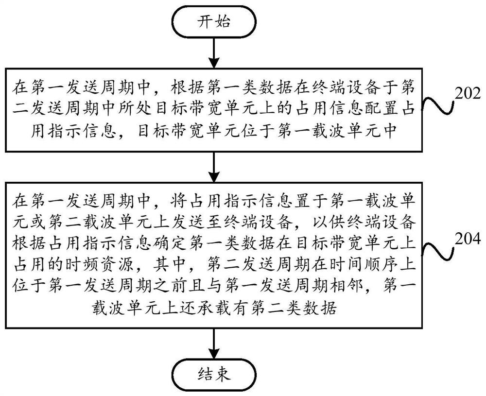
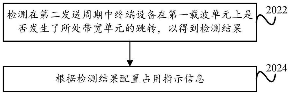
[0050] Combine below Figure 2 to Figure 5 The scheme of the data occupation indication method applicable to the network side device according to the embodiment of the present invention will be descri...


PUM


Abstract

The present invention proposes a data occupation indication method and device, network side equipment, and terminal equipment, wherein the method applicable to the network side equipment includes: in the first sending cycle, according to the first type of data, the terminal device in the second sending cycle The occupancy information on the target bandwidth unit located in the first carrier unit is used to configure the occupation indication information; in the first sending cycle, the occupation indication information is placed on the first carrier unit or the second carrier unit and sent to the terminal device , for the terminal device to determine the time-frequency resource occupied by the first type of data on the target bandwidth unit according to the occupation indication information, the second transmission period is located before the first transmission period in time sequence and the two are adjacent, and Also carries the second type of data. This solution configures the content of the occupation indication according to the condition of the bandwidth unit where the terminal device is in the transmission period of the occupation indication information, and can effectively optimize the information configuration mode of the occupation indication.

Description

technical field [0001] The present invention relates to the field of communication technology, in particular, to a data occupation indication method, a data occupation indication device, network side equipment and terminal equipment. Background technique [0002] At present, the research and development of the fifth generation mobile communication system (5G) is in full swing. According to future application requirements, the 5G system needs to support a variety of business scenarios, among which low-latency, high-reliability (Ultra-reliable and Low Latency Communications, URLLC) communication scenarios such as unmanned driving and industrial automation have attracted widespread attention. Usually, URLLC data is extremely bursty and has high requirements on delay, so this type of data has a very high resource scheduling priority. The existing solution proposed for the transmission of URLLC data is: when the URLLC data arrives, the 5G base station immediately schedules it, t...

Claims


Application Information

Patent Timeline
Patent Type & Authority Patents(China)
IPC IPC(8): H04L5/00
CPCH04L5/0091H04L5/0096
Inventor 赵思聪董贤东
Owner MEIZU TECH CO LTD
Learn More