part drilling machine

A technology for drilling machines and parts, which is applied in the direction of boring/drilling, drilling/drilling equipment, metal processing machinery parts, etc., which can solve the problems of excessive debris and labor, and achieve enlarged flushing area and good flushing effect Effect

Active Publication Date: 2020-04-10
昆山森雅毓电子科技有限公司
View PDF8 Cites 0 Cited by
  • Summary
  • Abstract
  • Description
  • Claims
  • Application Information

AI Technical Summary

Problems solved by technology

[0004] However, in actual use, it is found that when the parts are drilled, more debris will be generated at the position of the drilled holes, so the staff needs to hold a flushing tube to flush the punching area of ​​the parts to flush out the drilled holes resulting debris
However, this method requires the staff to manually rinse, which is laborious

Method used


Image

  • part drilling machine
  • part drilling machine
  • part drilling machine

Examples


Embodiment 1

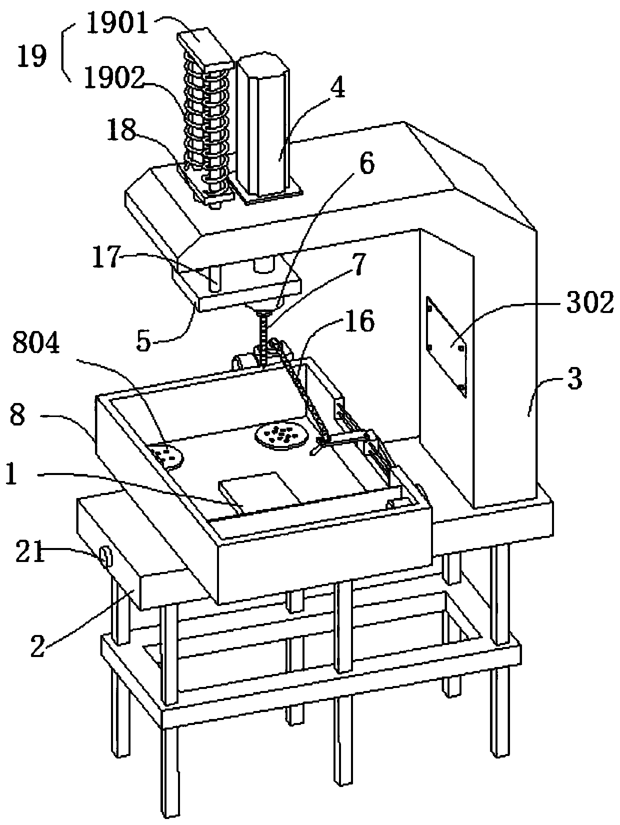
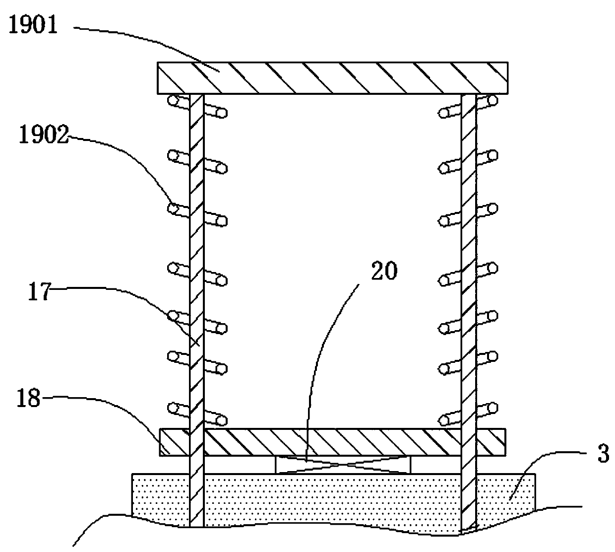
[0030] refer to figure 1 As shown, the present embodiment provides a part drilling machine, including a workpiece table 1, an underframe 2, a support arm 3 arranged on the underframe 2, a hydraulic cylinder 4 vertically arranged on the upper part of the support arm 3, and a mounting plate 5 vertically fixedly install the power head 6 on the output shaft of the hydraulic cylinder 4, and the drill bit 7 installed on the power head 6. Among them, the rotary head is mainly driven by the power head 6 to rotate, and the hydraulic cylinder 4 drives the power head 6 to move up and down to complete the drilling work.

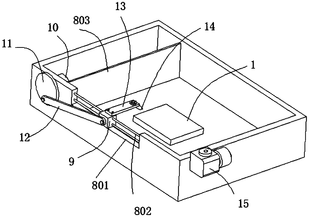
[0031] combine figure 2 As shown, it also includes a water tank 8 horizontally arranged on the chassis 2; the workpiece table 1 is arranged in the water tank 8; the side wall of the water tank 8 close to the support arm 3 is slidably connected with a slider 9; the water tank 8 passes through the partition 803 is divided into a working area and a water barrier area, wh...

Embodiment 2

[0046] On the basis of embodiment 1, in order to carry out drilling work more conveniently, embodiment 2 is provided here:

[0047] combine Figure 5 As shown, the side wall of the support arm 3 close to the side of the water tank 8 is provided with a light groove 301 with an LED lamp board 22 inside; wherein the notch of the light groove 301 is installed with a screw covering the notch of the light groove 301. A transparent cover plate 302 . The purpose of setting the LED lamp board 22 is to illuminate when drilling.

[0048] combine Figure 6 As shown, the LED light board 22 is electrically connected with an automatic control circuit; the automatic control circuit includes:

[0049] The light detection circuit 400 is used to detect the light intensity of the external environment, and output a corresponding light detection signal accordingly.

[0050] Specifically, the light detection circuit 400 includes a fifth resistor R5, a sixth resistor R6, a photosensitive resistor...


PUM


Abstract

The invention provides a part drilling machine. The part drilling machine comprises a workpiece table, a bottom frame, a supporting arm arranged on the bottom frame, a hydraulic cylinder vertically arranged on the upper portion of the supporting arm, a power head vertically and fixedly mounted on an output shaft of the hydraulic cylinder through a mounting plate, and a drill bit mounted on the power head and further comprises a water tank horizontally arranged on the bottom frame. The workpiece table is arranged in the water tank, and the side wall of the side, close to the supporting arm, ofthe water tank is slidably connected with a sliding block; and the water tank is partitioned into a working area and a water insulation area through a partition plate, wherein the workpiece table is located in the working area, a motor is arranged in the water insulation area, a rotating disc is fixedly connected to a main shaft of the motor, and the side faces on the same side of the rotating disc and the sliding blocks are connected through a connecting rod. The part drilling machine can flush parts when drilling the parts, and thus chippings generated during drilling are scoured off.

Description

technical field [0001] The invention relates to the technical field of drilling devices, in particular to a component drilling machine. Background technique [0002] Drilling machine, that is, a machine for drilling parts; [0003] Drilling machine in the prior art is usually made up of hydraulic cylinder, power head, and the drill bit that is located on the power head, drives drill bit to rotate by power head, and drives power head to press down by hydraulic cylinder, completes drilling work. [0004] However, in actual use, it is found that when the parts are drilled, more debris will be generated at the drilled position, so the staff needs to hold a flushing tube to flush the punching area of ​​the part to flush out the drilled holes resulting debris. However, this method requires the staff to manually rinse, which is laborious. Contents of the invention [0005] In view of this, the object of the present invention is to provide a part drilling machine. [0006] In ...

Claims


Application Information

Patent Timeline
Patent Type & Authority Patents(China)
IPC IPC(8): B23B39/00B23Q11/00
CPCB23B39/00B23Q11/0042
Inventor 覃德华
Owner 昆山森雅毓电子科技有限公司
Why Eureka
Try Eureka