Jolt-ramming system for concrete pouring and concrete pouring jolt-ramming technology

A concrete and solid box technology, applied in construction, building structure, construction material processing and other directions, can solve the problems of too fast pulling out, poor vibrating effect, slow insertion, etc. Good, simple process effect

Active Publication Date: 2018-12-04
中国电建集团湖北工程有限公司
View PDF5 Cites 3 Cited by
  • Summary
  • Abstract
  • Description
  • Claims
  • Application Information

AI Technical Summary

Problems solved by technology

[0004] In order to solve the above problems, the present invention provides a vibrating system for concrete pouring and a concrete pouring vibration process, which can solve the problems of non-perpendicularity, slow insertion, and fast pull-out of the vibrating rod when the concrete is poured, and vibration effects. It can realize the automatic vibration function of concrete, which has the advantages of simple process, the vibration process meets the process requirements, good vibration effect and high work efficiency.

Method used


Image

  • Jolt-ramming system for concrete pouring and concrete pouring jolt-ramming technology
  • Jolt-ramming system for concrete pouring and concrete pouring jolt-ramming technology
  • Jolt-ramming system for concrete pouring and concrete pouring jolt-ramming technology

Examples


Embodiment Construction

[0023] In order to make the technical means, creative features, goals and effects achieved by the present invention easy to understand, the present invention will be further described below in conjunction with specific illustrations. It should be noted that, in the case of no conflict, the embodiments in the present application and the features in the embodiments can be combined with each other.

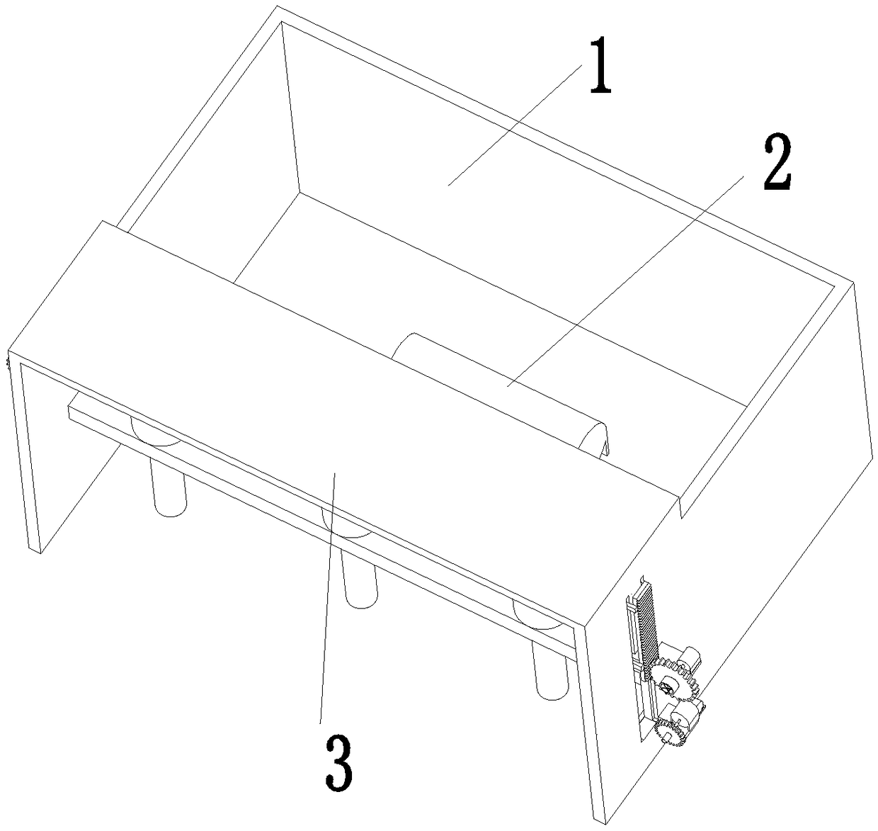
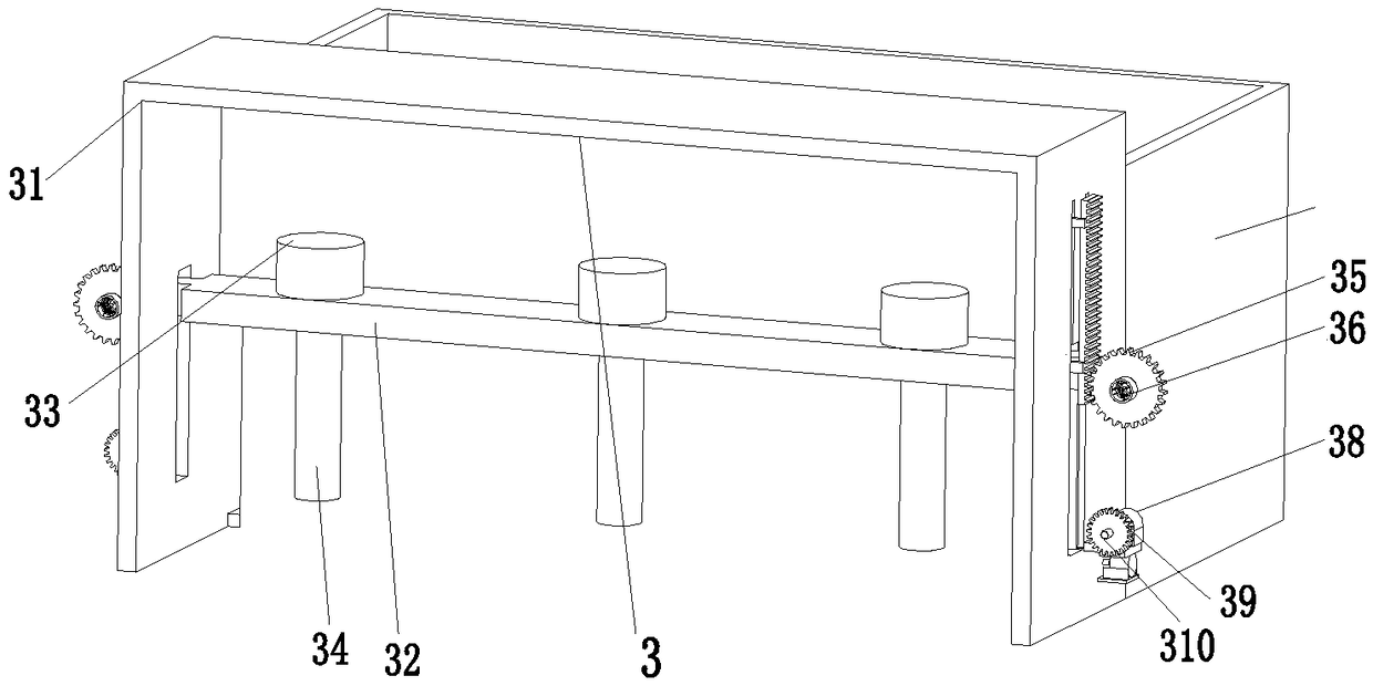
[0024] Such as Figure 1 to Figure 6 As shown, a vibrating system for concrete pouring includes a vibrating box 1, a vibrating motor 2 and a vibrating device 3, the inside of the vibrating box 1 is equipped with a vibrating motor 2, and the front end surface of the vibrating box 1 A vibration device 3 is installed.

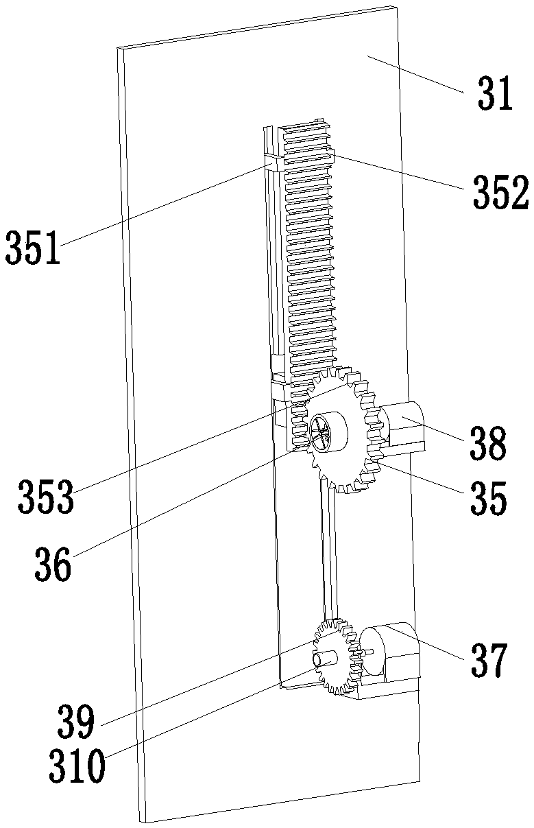
[0025]Described vibrating device 3 comprises a vibrating mounting frame 31, and the left and right sides of the vibrating mounting frame 31 are provided with through holes, and a vibrating connecting plate 32 is installed in the through hole by a sliding fit mode, and t...


PUM


Abstract

The invention relates to a jolt-ramming system for concrete pouring and a concrete pouring jolt-ramming technology. The jolt-ramming system comprises a jolt-ramming box, a jolt-ramming motor and a jolt-ramming device; the jolt-ramming motor is mounted inside the jolt-ramming box, the jolt-ramming device is mounted on the front end face of the jolt-ramming box, the jolt-ramming device comprises a jolt-ramming mounting frame, and through holes are formed in the left and right side faces of the jolt-ramming mounting frame; a jolt-ramming connecting plate is mounted in the through holes in a sliding fit mode, circular holes are formed in the jolt-ramming connecting plate, vibration motors are evenly mounted on the upper end face of the jolt-ramming connecting plate, vibration rods are mountedat the lower ends of the vibration motors, and the vibration rods penetrate through the circular holes; and jolt-ramming mechanisms are mounted on the right side face of the jolt-ramming connecting plate. According to the jolt-ramming system for concrete pouring and the concrete pouring jolt-ramming technology, the problems that in the concrete pouring process, the vibration rods are not vertically inserted into concrete, are inserted into the concrete excessively slowly and are pulled out of the concrete excessively quickly, the jolt-ramming effect is poor, and the working efficiency is low can be solved; and an automatic jolt-ramming function on the concrete can be achieved, and the jolt-ramming system for concrete pouring and the concrete pouring jolt-ramming technology have the advantages that the technology is simple, the jolt-ramming process conforms to the technological requirements, the jolt-ramming effect is good, and the working efficiency is high.

Description

technical field [0001] The invention relates to the field of construction, in particular to a vibrating system for pouring concrete and a vibrating process for pouring concrete. Background technique [0002] With the acceleration of the level of urbanization, more and more buildings and roads are being built in the city, and most of the buildings in residential areas use concrete frame structures, which have good stability and earthquake resistance. , so the concrete needs to be vibrated when pouring concrete to achieve a good stability effect, and the vibrator in the existing equipment has certain disadvantages when it is working. [0003] According to the concrete material and pouring process requirements, when vibrating the concrete, the vibrating rod should be inserted vertically and quickly into the concrete. When pulling out the vibrating rod, the concrete needs to be pulled out slowly, so as to avoid leaving behind In the existing vibrator, most of the vibrating rods...

Claims


Application Information

Patent Timeline
Patent Type & Authority Applications(China)
IPC IPC(8): E04G21/08
CPCE04G21/08
Inventor 曹玉娣
Owner 中国电建集团湖北工程有限公司
Why Eureka
Try Eureka