An impeller structure for a compressor or a blower

A technology of blowers and compressors, applied to components of pumping devices for elastic fluids, machines/engines, mechanical equipment, etc.

Active Publication Date: 2020-04-03
HANGZHOU GRNIS ENERGY SAVING TECH CO LTD
View PDF7 Cites 0 Cited by
  • Summary
  • Abstract
  • Description
  • Claims
  • Application Information

AI Technical Summary

Problems solved by technology

However, there is still a lot of room for improvement in the existing products to improve product performance.

Method used


Image

  • An impeller structure for a compressor or a blower
  • An impeller structure for a compressor or a blower
  • An impeller structure for a compressor or a blower

Examples


Embodiment Construction

[0018] The present invention will be further described in detail below in conjunction with the accompanying drawings.

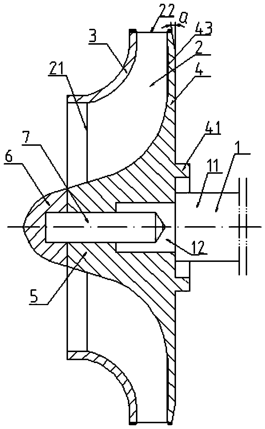
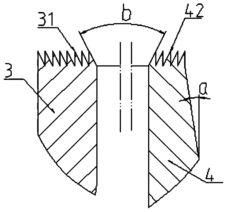
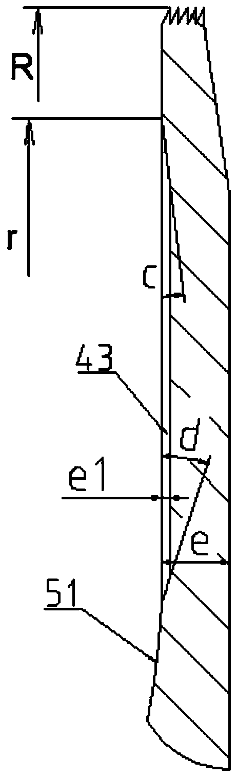
[0019] see attached Figure 1-3 : The impeller structure for a compressor or a blower includes a rotating shaft 1, a first diameter section 11, a second diameter section 12, a blade 2, a leading edge 21, a trailing edge 22, a front disc 3, a toothed seal 31, and a rear disc 4. , Rear disc sealing ring 41 , toothed seal 42 , bypass channel 43 , hub 5 , arc segment 51 , arc nut 6 , threaded connection 7 .

[0020] The rotor includes a rotating shaft 1 and an impeller. The rotating shaft 1 includes a first diameter section 11 and a second diameter section 12 in turn, and their diameters decrease in turn; The outer circumference of the threaded connector 7 has an external thread, one end of the threaded connector 7 is threaded with the second diameter section 12, this end is screwed into the inner threaded hole of the second diameter section 12, and the other end...


PUM


Abstract

An impeller structure for a compressor or a blower, including a shaft (1) and an impeller, the shaft includes a first diameter section (11) and a second diameter section (12), and the impeller is mounted on the shaft through a threaded connection and an arc nut , characterized in that: a bypass channel (43) is provided on the inner side of the rear disc (4), the bypass channel 43 is an annular groove, the depth of the bypass channel 43 is e1, and the bypass channel is located radially outside the hub. The impeller structure increases the flow before the impeller outlet, improves the anti-cavitation performance of the impeller, reduces the probability of surge, and increases the sealing performance at the impeller outlet.

Description

technical field [0001] The invention relates to the field of fluid machinery, in particular to an impeller structure for a compressor or a blower. Background technique [0002] A compressor or a blower is a fluid mechanical device that converts mechanical energy into fluid energy with gas as the working medium. The impeller structure plays a crucial role in the efficiency and performance of the entire device. However, there is still a lot of room for improvement in the improvement of product performance in the existing products. SUMMARY OF THE INVENTION [0003] The purpose of the present invention is to overcome the deficiencies in the prior art and provide an impeller structure for a compressor or a blower, which increases the flow before the impeller outlet and improves the resistance of the impeller. Cavitation performance reduces the probability of surge and increases sealing at the impeller outlet. [0004] In order to achieve the above object, the technical scheme...

Claims


Application Information

Patent Timeline
Patent Type & Authority Patents(China)
IPC IPC(8): F04D29/28
CPCF04D29/083F04D29/281F04D29/284F04D29/667
Inventor 赵浩浩
Owner HANGZHOU GRNIS ENERGY SAVING TECH CO LTD
Why Eureka
Try Eureka