
Cell production and staining machine

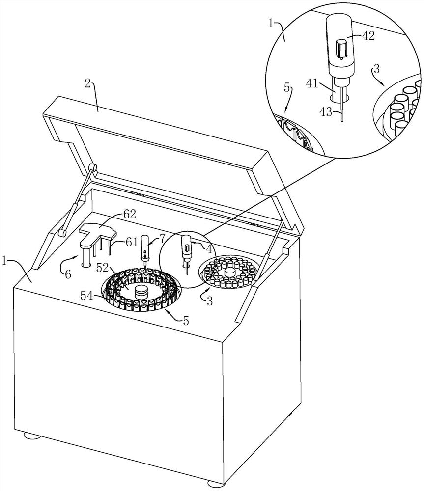
A technology of cell production and all-in-one machine, which is applied in the preparation, sampling, and instrumentation of test samples, and can solve the problems of residual waste liquid and affecting the observation and use of slide 542.

Active Publication Date: 2020-09-18
BEIJING CHENGZHI GUANGHUI TECH CO LTD
View PDF9 Cites 0 Cited by
  • Summary
  • Abstract
  • Description
  • Claims
  • Application Information

AI Technical Summary

Problems solved by technology

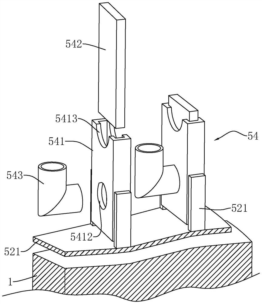
When the waste liquid treatment mechanism 6 extracts waste liquid from each centrifuge cylinder 543, the waste liquid inside the centrifuge cylinder 543 waiting to extract the waste liquid will soak the prepared glass slides, thereby affecting the observation and use of the slides 542.
[0012] And when the waste liquid treatment mechanism extracts waste liquid, there will be a certain gap between the waste liquid suction pipe 61 and the centrifuge cylinder 543 to reduce the collision, so there will be more waste liquid remaining

Method used


Image

  • Cell production and staining machine
  • Cell production and staining machine
  • Cell production and staining machine

Examples


Embodiment 1

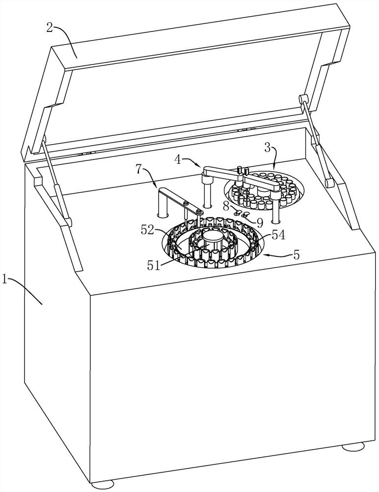
[0064] Such as image 3 As shown, an all-in-one cell production and staining machine includes a workbench 1 and a safety cover 2 hinged on the workbench 1 at one end. When the safety cover 2 is closed, it is fastened with the workbench 1 to form a space. A sample storage mechanism 3 , a pipetting mechanism 4 , a centrifugal mechanism 5 , and a dyeing mechanism 7 are distributed on the surface of the workbench 1 in this space.

[0065] Firstly, the prepared cell suspensions of various samples are placed in the sample storage mechanism 3 . The sample storage mechanism 3 includes a turntable controlled by a motor, and the motor is arranged in the space inside the workbench 1 . The motor is selected as a servo motor, and a number of holding dishes are detachably fixed on the turntable along its circumferential direction, and the holding dishes are used to place the prepared sample cell suspension.

[0066] The centrifugal mechanism 5 includes a centrifugal turntable 52, the cen...

Embodiment 2

[0095] An all-in-one cell production and staining machine, such as Figure 9 As shown, the pipetting mechanism 4 includes a pipetting needle 43 , and a rotating arm 42 that fixes the pipetting needle 43 and drives the pipetting needle 43 to approach or move away from the workbench 1 . The rotating arm 42 is controlled by the elevating rod 41 stretching out from the workbench 1, and the elevating rod 41 can drive the rotating arm 42 to rotate or lift.

[0096] A cleaning tank 8 and a drying tank 9 are provided on the workbench 1 between the centrifugal mechanism 5 and the waste liquid treatment mechanism 6 .

[0097] combine Figure 11 , There are two pipetting mechanisms 4, and one end of the two pipetting mechanisms 4 fixing the pipetting needle 43 is arranged oppositely. The cleaning tank 8 and the drying tank 9 are arranged on the rotation path of the pipetting needle 43 . After one pipetting is completed, the lifting rod 41 controls the rotating arm 42 to rotate to the ...


PUM


Abstract

The invention discloses a cell preparation staining integrated machine which belongs to the field of biology experiments. The machine includes a centrifugal rotary plate slidably connected to a centrifugal shaft and rotating with the centrifugal shaft; centrifugal cylinders arranged circumferentially on the centrifugal rotary plate and used for holding a cell suspending liquid; waste liquid outlets penetrating side walls of the centrifugal cylinders close to the centrifugal rotary plate; a positioning plate fixed on the centrifugal shaft and located under the centrifugal rotary plate; a lifting member disposed on the positioning plate and controlling the centrifugal rotary plate to move along the centrifugal shaft toward or away from the positioning plate; and positioning columns extendingout of the positioning plate through the centrifugal rotary plate, and closing or leaving the waste liquid outlets when the centrifugal rotary plate moves along the centrifugal shaft toward or away from the positioning plate. According to the scheme, pumping treatment can be simultaneously performed on all the centrifugal cylinders, thus reducing the influence of waste liquid soaking on observation of the slide.

Description

technical field [0001] The invention relates to the field of biological experiment equipment, in particular to an integrated cell film production and dyeing machine. Background technique [0002] Such as figure 1 As shown, the all-in-one cell production and staining machine usually includes a workbench 1 and a safety cover 2 hinged on the workbench 1 at one end. When the safety cover 2 is closed, it is fastened with the workbench 1 to form a space. A sample storage mechanism 3 , a pipetting mechanism 4 , a centrifugal mechanism 5 , a waste liquid treatment mechanism 6 , and a dyeing mechanism 7 are distributed on the surface of the workbench 1 in this space. [0003] Firstly, the prepared cell suspensions of various samples are placed in the sample storage mechanism 3 . The sample storage mechanism 3 includes a turntable controlled by a motor, and the motor is arranged in the space inside the workbench 1 . The motor is selected as a servo motor, and a number of holding d...

Claims


Application Information

Patent Timeline
Patent Type & Authority Patents(China)
IPC IPC(8): G01N1/31G01N1/28
CPCG01N1/2813G01N1/31G01N2001/2846
Inventor 夏炜
Owner BEIJING CHENGZHI GUANGHUI TECH CO LTD
Learn More