
Boiler washing device

A water washing device and boiler technology, which is applied in the direction of drying gas arrangement, dryer, chemical instruments and methods, etc., can solve the problem of inconvenient confirmation of the cleanliness of the boiler surface

Inactive Publication Date: 2019-03-08
WUHU MINGREN THERMAL ENERGY EQUIP
View PDF4 Cites 0 Cited by
  • Summary
  • Abstract
  • Description
  • Claims
  • Application Information

AI Technical Summary

Problems solved by technology

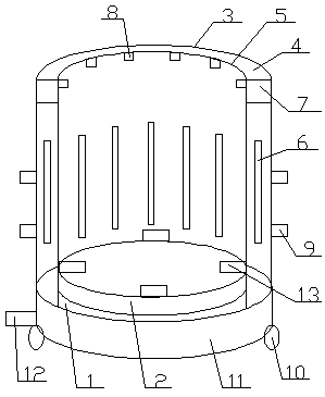
[0003] Aiming at the deficiencies of the prior art, the present invention provides a boiler water washing device, which solves the problem that it is inconvenient for personnel to confirm whether the boiler surface is clean after water washing. The present invention adopts the following technical solutions to solve the technical problem: including the base, There is a rotating table on the top of the base, an outer shell is arranged behind the rotating table, a connecting plate is arranged on the top of the outer shell, and a protective plate is connected to the other end of the connecting plate. The protective plate is located between the outer shell and the rotating table, and the outer shell and the protective plate They are all quartz glass plates, and there are several LED lights on the front wall of the outer shell. The number of LED lights is determined according to the actual production demand. There is a hot air circulation pipe at the bottom of the connecting plate. There are several nozzles on the hot air circulation pipe. The number of nozzles is based on the actual The production demand is determined, the other end of the nozzle passes through the protective plate and protrudes to the front of the protective plate, the left and right ends of the outer shell are equipped with snap rings, and the bottom of the outer shell is equipped with universal wheels

Method used


Image

  • Boiler washing device

Examples


Embodiment Construction

[0011] In order to deepen the understanding of the present invention, the present invention will be further described below in conjunction with the examples, which are only used to explain the present invention, and do not constitute a limitation to the protection scope of the present invention.

[0012] Such as figure 1 As shown, this embodiment provides a boiler water washing device, which includes a base 1, a rotary table 2 is provided on the top of the base 1, and a latch 13 is provided on the top hinge of the rotary table 2. After the boiler is placed on the rotary table 2, the card The bolt 13 fixes the boiler, the outer shell 3 is arranged behind the rotary table 2, the connecting plate 4 is arranged on the top of the outer shell 3, and the other end of the connecting plate 4 is connected with a protective plate 5, and the protective plate 5 is located between the outer shell 3 and the rotary table 2. Between, the diameter of the protection plate 5 is greater than that ...


PUM


Abstract

The invention provides a boiler washing device, which comprises a base. A rotating table is arranged at the top of the base, an outer shell is arranged behind the rotating table, and a connecting plate is arranged at the top of the outer shell; the other end of the connecting plate is connected with a protective plate, the protective plate is located between the outer shell and the rotating table,and the outer shell and the protective plate are both silica glass plates; an LED lamp is arranged on the front wall of the outer shell, a hot air circulating pipeline is arranged at the bottom of the connecting plate, and a spraying head is arranged on the hot air circulating pipeline; and the other end of the spraying head penetrates through the protective plate to extend out towards the frontpart of the protective plate, clamping rings are arranged at the left and right ends of the outer shell correspondingly, and universal wheels are arranged at the bottom of the outer shell. According to the boiler washing device, by arranging the spaying head facing the surface of a boiler, water on the cleaned area on the boiler is blow-dried by hot air, then the cleaned area on the boiler is rotated back, thus the influence of dirty water on personnel observation is reduced, and the cleaning efficiency of the boiler is improved.

Description

technical field [0001] The invention relates to the technical field of thermal energy equipment, in particular to a boiler water washing device. Background technique [0002] A hot water boiler is a boiler that produces hot water. The existing hot water boilers are usually large and can burn a lot of hot water at one time. However, after a long period of use, dirt will accumulate on the surface of the hot water boiler, which needs to be cleaned. , when cleaning, use a portable water spray gun to wash with water. Since there are a lot of dust and other dirt on the surface of the boiler, it will be wet after being soaked in water, which makes it inconvenient for personnel to confirm whether the surface of the boiler is clean, making the cleaning efficiency of the boiler low. , it is very necessary to solve this problem. Contents of the invention [0003] Aiming at the deficiencies of the prior art, the present invention provides a boiler water washing device, which solves t...

Claims


Application Information

Patent Timeline
IPC IPC(8): B08B3/02B08B13/00F26B21/00
CPCB08B3/022B08B13/00F26B21/004
Inventor 洪佳佳
Owner WUHU MINGREN THERMAL ENERGY EQUIP
Learn More