Feeding device of strip sticking machine

A feeding device and sticking machine technology, which is applied in the direction of sending objects, thin material processing, transportation and packaging, etc., can solve the problems of low efficiency, achieve the effect of accurate position, improve production efficiency, and simple structure

Pending Publication Date: 2018-12-07
CHANGZHOU ZHIGU ELECTROMECHANICAL TECH CO LTD
View PDF3 Cites 3 Cited by
  • Summary
  • Abstract
  • Description
  • Claims
  • Application Information

AI Technical Summary

Problems solved by technology

At present, most of these processes are glued by hand, and the efficiency is too low

Method used


Image

  • Feeding device of strip sticking machine
  • Feeding device of strip sticking machine
  • Feeding device of strip sticking machine

Examples


Embodiment 1

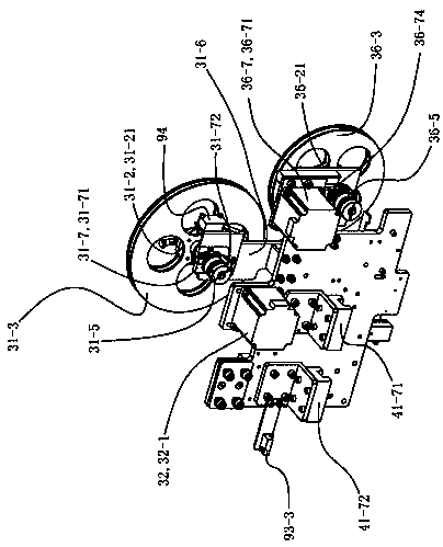
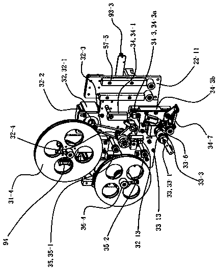
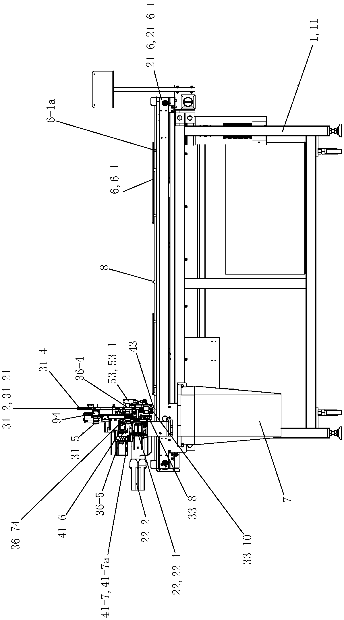
[0078] See Figure 1 to Figure 8 and Figure 14 to Figure 22 , The feeding device 3 includes a discharge tray assembly 31 , an active feeding assembly 32 , a feeding detection assembly 33 , a clamping assembly 34 , a guide wheel assembly 35 and a waste collection assembly 36 .

[0079] The discharge tray assembly 31 includes a discharge tray support shaft 31-1, a discharge tray bottom plate 31-2, a left stop tray 31-3, a right stop tray 31-4, and a first adjustable damping coupling 31-5 , The discharge tray mounting seat 31-6 and the first limiting device 31-7. The discharge tray mounting seat 31-6 is fixedly arranged on the middle upper part of the Y-axis first mounting seat plate 22-11 of the Y-axis module 22 of the tape sticking machine. The discharge tray support shaft 31-1 is arranged on the top of the discharge tray mounting seat 31-6 along the left and right rotation through corresponding bearings and bearing seats. The middle part of the bottom plate 31-2 of the dis...


PUM


Abstract

The invention discloses a feeding device of a strip sticking machine, which is characterized in that the feeding device comprises an active feeding component, a material clamping component and a wastematerial receiving component. The material clamping component is used for clamping or loosening the hot melt adhesive film strip. The active feeding component carries out the conveying and feeding ofthe hot melt adhesive film strip, and the waste material receiving component is used for collecting the isolating paper layer of the hot melt adhesive film strip.

Description

technical field [0001] The invention relates to the field of garment processing equipment, in particular to a feeding device of a tape sticking machine for sticking hot melt adhesive films on garment fabrics. Background technique [0002] Clothing is a product that is sewn with fabrics and worn on the human body for protection and decoration, also known as clothes. The clothing that appeared at the beginning was mainly for the purpose of concealing shame. After the development of time, it turned to practicality, and at the same time, more attention was paid to the aesthetics of clothing. Factors affecting aesthetics include fabric texture, color, pattern, shape retention, drape, elasticity, wrinkle resistance, clothing style, etc. [0003] Quilting is the molding that holds the filling and lining to the face. The quilting thread of the traditional down jacket will damage the fabric (with pinholes), and the fine down may leak from the pinholes of the quilting thread, thereb...

Claims


Application Information

Patent Timeline
Patent Type & Authority Applications(China)
IPC IPC(8): A41H43/02B65H35/06
CPCA41H43/0235B65H35/06
Inventor 陈中华
Owner CHANGZHOU ZHIGU ELECTROMECHANICAL TECH CO LTD
Why Eureka
Try Eureka