Vibration device for bag-type dust collector
A bag filter and vibration device technology, applied in chemical instruments and methods, dispersed particle separation, dispersed particle filtration, etc., can solve the problems of affecting the dust removal effect, reducing the reuse performance of the filter element, and small jitter deformation, so as to improve work efficiency. , resource saving, efficient collision effect
- Summary
- Abstract
- Description
- Claims
- Application Information
AI Technical Summary
Problems solved by technology
Method used
Image
Examples
Embodiment 1
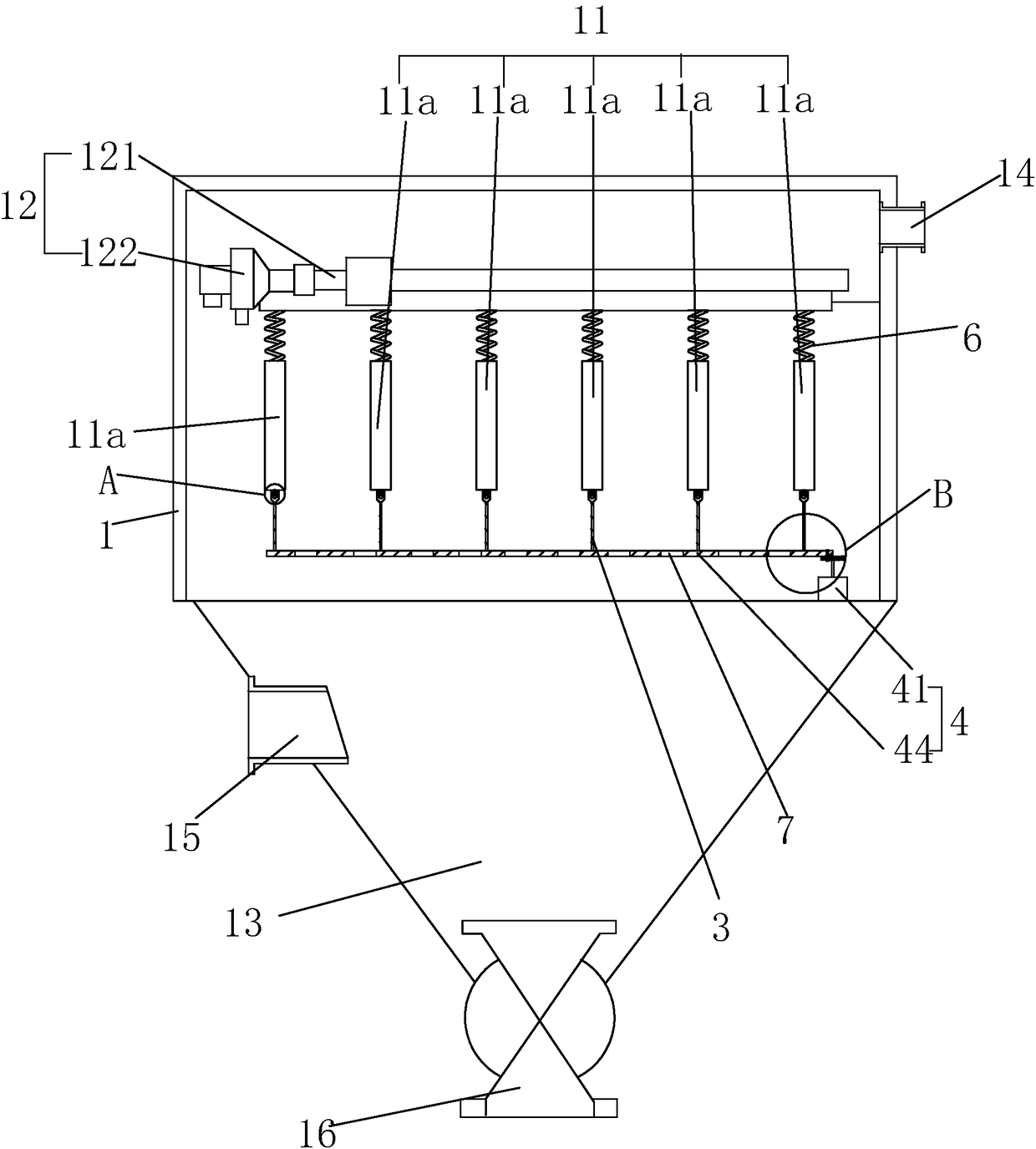
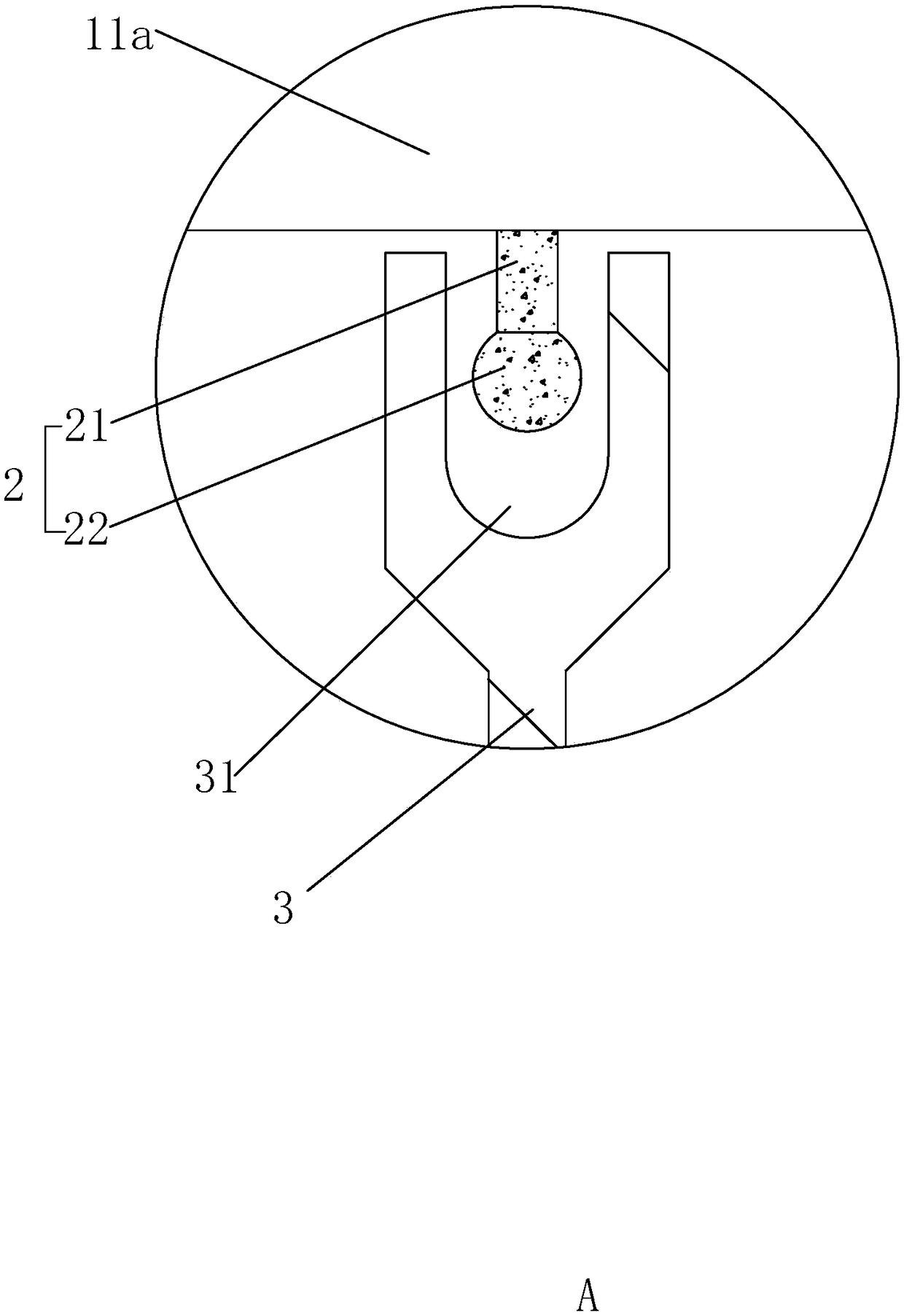
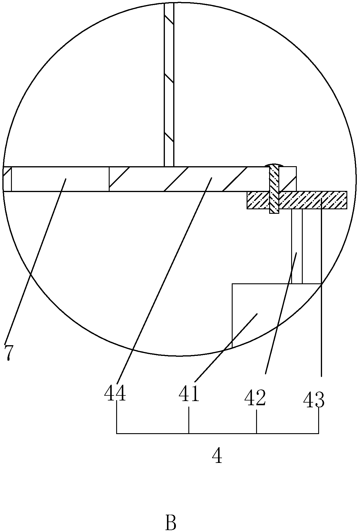
[0034] Embodiment 1: a kind of vibration device used in the bag filter, such as figure 1 Shown, mainly comprises body 1, is provided with a plurality of filter elements 11a in body 1, and filter element 11a is arranged in the body 1 in row-and-column array, is positioned at the top of filter element 11a in body 1 and is provided with cleaning control system 12, cleaning The control system 12 mainly includes an injection pipe 121 fixedly arranged in the body 1 above the filter element 11a. The injection pipe 121 is provided with an electromagnetic pulse valve 122. At this time, a plurality of filter elements 11a arrayed along the horizontal direction of the injection pipe 121 are defined to form a Group filter assembly 11; in the body 1, below the filter element 11a, there is an ash hopper 13 for dust storage. In the gas, there is a clean gas outlet 14 for clean gas discharge above the dust removal control system 12. The side of the ash hopper 13 The wall is provided with a dus...
specific Embodiment approach
[0037]Specific implementation method: when the filter core 11a accumulates a lot of dust near the middle and lower parts and cannot fall smoothly under the work of the dust removal control system 12, the drive motor 41 is controlled to work, the output shaft 42 rotates, and drives the connecting disc 43 Circumferential rotation, now can drive the movement of the connecting rod 44 hinged with the connecting disc 43, that is, one end of the connecting rod 44 hinged with the connecting disc 43 moves in a circle along with the connecting disc 43, because the impact body 2 is located in the impact sleeve 31, the restricting effect on the connecting rod 44 can be achieved, that is, the range of motion of the connecting rod 44 is limited, so that the end of the connecting rod 44 away from the connecting disc 43 can only swing in a small range. When swinging, it can drive the swing of a plurality of fixed rods 3 connected thereto, so that the inner wall of the impact sleeve 31 collides...
Embodiment 2
[0040] Embodiment 2: a kind of vibration device used in the bag filter, the difference from embodiment 1 is, as Figure 4 and 5 As shown, at this time, the strut 21 of the impact body 2 is hingedly arranged at the bottom of the filter core 11a, and an electromagnet 311 controlled by a circuit signal is provided in the impact sleeve 31, and the electromagnet 311 can realize the adsorption of the impact body 2 effect.
[0041] When the staff checks that there is only a large amount of dust accumulated on the individual filter elements 11a in the dust collector, they can control the electromagnet 311 in the sleeve 31 at the bottom of the corresponding filter element 11a to make it energized, and the electromagnet 311 After being energized, the impact body 2 will be adsorbed, so that the impact body 2 swings until it is attracted to the electromagnet 311, and then the electromagnet 311 is controlled to lose power. At this time, after losing the suction force of the electromagnet ...
PUM
 Abstract
Description
Claims
Application Information
 - R&D
- Intellectual Property
- Life Sciences
- Materials
- Tech Scout
- Unparalleled Data Quality
- Higher Quality Content
- 60% Fewer Hallucinations
Browse by: Latest US Patents, China's latest patents, Technical Efficacy Thesaurus, Application Domain, Technology Topic, Popular Technical Reports.
© 2025 PatSnap. All rights reserved.Legal|Privacy policy|Modern Slavery Act Transparency Statement|Sitemap|About US| Contact US: help@patsnap.com


