Flotation machine transmission device

A transmission device and flotation machine technology, applied in flotation, solid separation, etc., can solve problems such as grease failure, high-power input structure actual operation difficulties, affecting the service life of the transmission structure and maintenance costs, etc., to reduce maintenance, The effect of large power input and reduced downtime

Pending Publication Date: 2018-12-07
BGRIMM MACHINERY & AUTOMATION TECH CO LTD +1
View PDF0 Cites 2 Cited by
  • Summary
  • Abstract
  • Description
  • Claims
  • Application Information

AI Technical Summary

Problems solved by technology

The temperature of the compressed air in the air supply pipeline is often as high as 80 degrees, which exceeds the temperature range of ordinary grease. Long-term use will cause the grease inside the transmission device and the rotary joint to fail, thus affecting the service life and maintenance of the entire transmission structure. cost;
[0010] The motor is directly connected to the main shaft and driven by a frequency converter. It is generally used in small flotation machines, especially laboratory flotation machines. For large flotation machines, it is difficult to input high power both in structure and in actual operation.

Method used


Image

  • Flotation machine transmission device
  • Flotation machine transmission device
  • Flotation machine transmission device

Examples


specific Embodiment approach

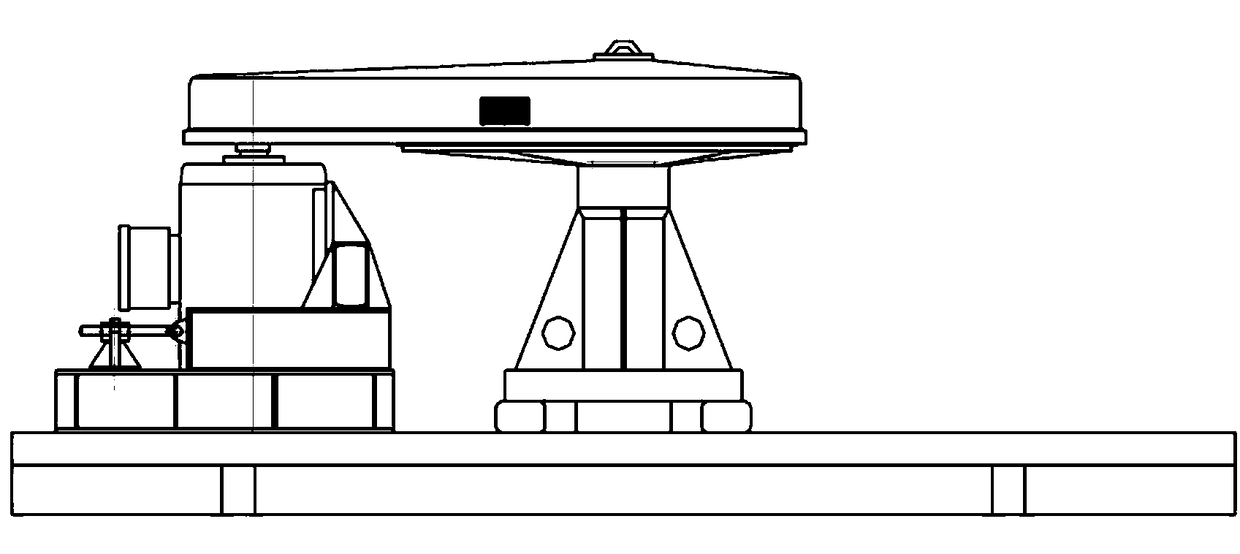
[0023] Flotation machine transmission device of the present invention, its preferred embodiment is:

[0024] Including reduction box, upper hollow shaft, motor support frame, auxiliary oil tank and lubricating oil circulation pump;

[0025] The upper hollow shaft is installed in the reduction box body and serves as the output shaft of the reduction box body, the motor bracket is arranged on the upper part of the reduction box body, and the input shaft of the reduction box body is connected with the high speed end coupling The motor shaft is connected and parallel to the upper hollow shaft.

[0026] The upper hollow shaft passes through the reduction box body longitudinally, the upper end of the upper hollow shaft is provided with a compressed air pipe joint, and the lower end is provided with a lower shaft connection flange.

[0027] A vacuum insulation layer is provided on the inner wall of the upper hollow shaft.

[0028] The lower part of the reduction box body is provide...

specific Embodiment

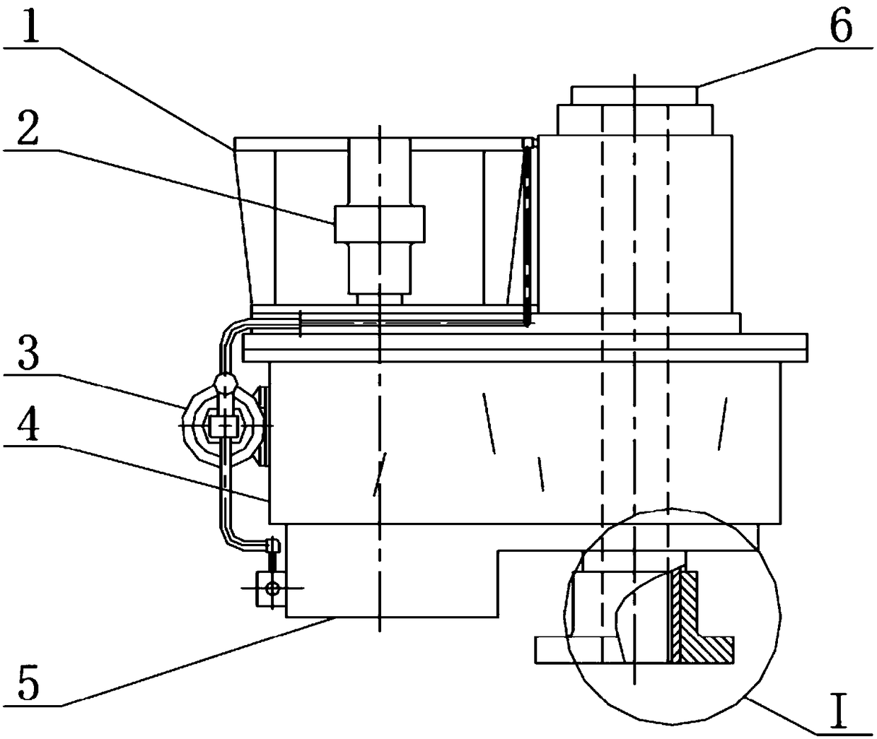
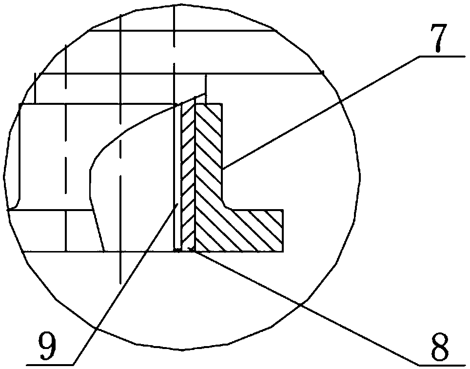
[0031] Such as Figure 2 to Figure 4 As shown, the driving motor is installed vertically downward on the motor bracket 1 through the flange, and the output shaft of the motor is connected to the input end of the high-speed shaft of the transmission device through the coupling 2; the reduction box body 4 is equipped with multi-stage reduction gears and the upper hollow shaft 8. A compressed air pipe joint 6 is provided at the upper end of the upper hollow shaft, and a flange 7 connected to the lower shaft is provided at the lower end of the upper hollow shaft 8. For heat insulation, a vacuum insulation layer 9 is provided on the inner wall of the upper hollow shaft The entire transmission device is lubricated with thin oil, and the reduction box body 4 is filled with lubricating thin oil, and an auxiliary oil tank 5 is provided at the bottom of the reduction box body 4. At the upper bearing seat of the box body 4.

[0032] Effect of the present invention:

[0033] The upper s...


PUM


Abstract

The invention discloses a flotation machine transmission device. The flotation machine transmission device comprises a speed reduction box body, an upper hollow shaft, a motor supporting frame, an auxiliary oil tank and a lubricating oil circulating pump, the upper hollow shaft is arranged in the speed reduction box body and serves as an output shaft of the speed reduction box body, the motor supporting frame is arranged at the upper part of the speed reduction box body, the input shaft of the speed reduction box body is connected with a motor shaft through a high-speed end coupler and is parallel to the upper hollow shaft, the upper hollow shaft longitudinally penetrates through the speed reduction box body, a compressed air pipe joint is arranged at the upper end of the upper hollow shaft, a lower shaft connecting flange is arranged at the lower end of the upper hollow shaft, a vacuum heat insulation layer is arranged on the inner wall of the upper hollow shaft, the auxiliary oil tank is arranged at the lower part of the speed reduction box body, and lubricating oil in the auxiliary oil tank is circularly injected to a bearing seat at the upper part of the speed reduction box body through the lubricating oil circulating pump. The transmission structure of a speed reducer is compact, the power input is large, the operation efficiency is high, the operation and the maintenanceare easy and convenient, and the transmission device is particularly suitable for the development requirements of large flotation equipment for energy conservation and consumption reduction, reductionof maintenance and reduction of shutdown time.

Description

technical field [0001] The invention relates to an inflatable mechanical stirring type flotation machine, in particular to a transmission device of the flotation machine. Background technique [0002] The inflatable mechanical stirring flotation machine is mainly composed of a transmission device, a main shaft mechanism, an inflatable pipeline, an impeller stator system and a tank body. At present, the transmission device of the flotation machine generally adopts belt transmission. This transmission method is simple in structure and easy to adjust, so it has been widely used in the development history of the flotation machine. However, with the further maturity of the flotation machine technology and the enlargement of the flotation machine with the continuous expansion of the mine scale, the shortcomings of the low efficiency of the belt drive are increasingly exposed. The transmission efficiency is low and the life of the wearing parts is short. Energy consumption and dai...

Claims


Application Information

Patent Timeline
Patent Type & Authority Applications(China)
IPC IPC(8): B03D1/16
CPCB03D1/16
Inventor 赖茂河王青芬韩登峰张明卢世杰陈东沈政昌张建辉
Owner BGRIMM MACHINERY & AUTOMATION TECH CO LTD
Why Eureka
Try Eureka