Clamping method for automobile welding

A technology for automobiles and workpieces, applied in the field of automobile welding clamping, can solve the problems affecting the work efficiency, product quality, reducing product accuracy, affecting the welding effect, etc., to achieve low production cost, improved pressing effect, and convenient installation. Effect

Inactive Publication Date: 2018-12-07
汪思芳
View PDF0 Cites 1 Cited by
  • Summary
  • Abstract
  • Description
  • Claims
  • Application Information

AI Technical Summary

Problems solved by technology

However, the existing welding fixtures have some disadvantages during use. First, the size of the fixture itself is fixed, but the metal materials to be welded are of different sizes, so often there will be inconsistency between the fixtures. This will directly affect the efficiency of work and the quality of products; secondly, most of the existing fixtures only limit a single degree of freedom. When clamping materials on curved surfaces, there will often be a little slip, but This greatly affects the welding effect and reduces the accuracy of the product

Method used


Image

  • Clamping method for automobile welding
  • Clamping method for automobile welding
  • Clamping method for automobile welding

Examples


Embodiment Construction

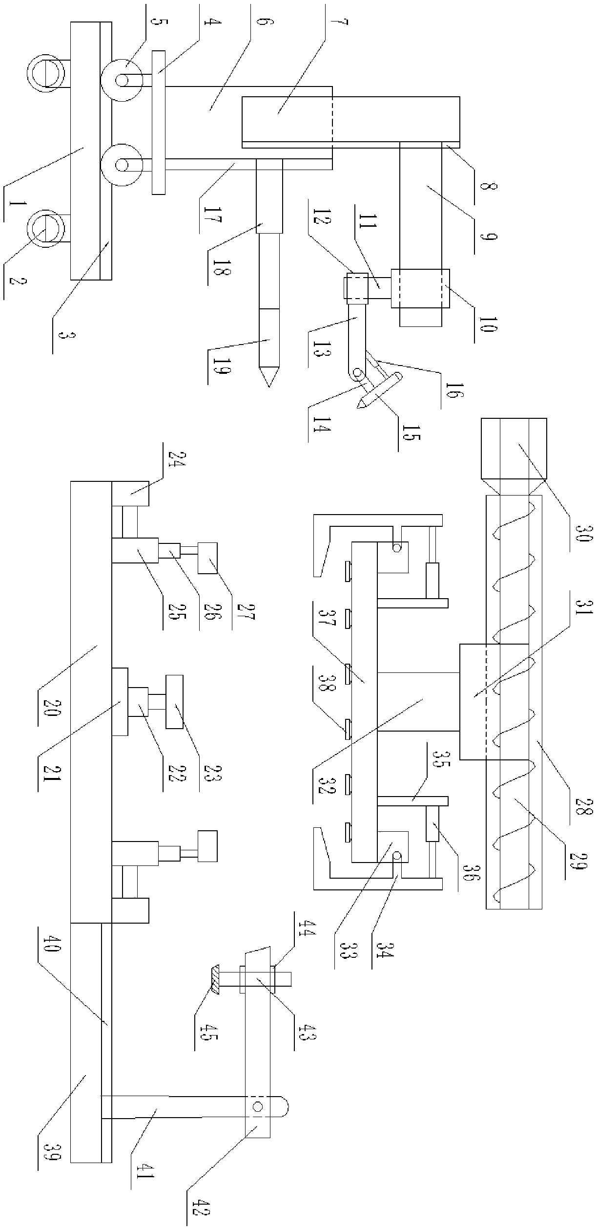
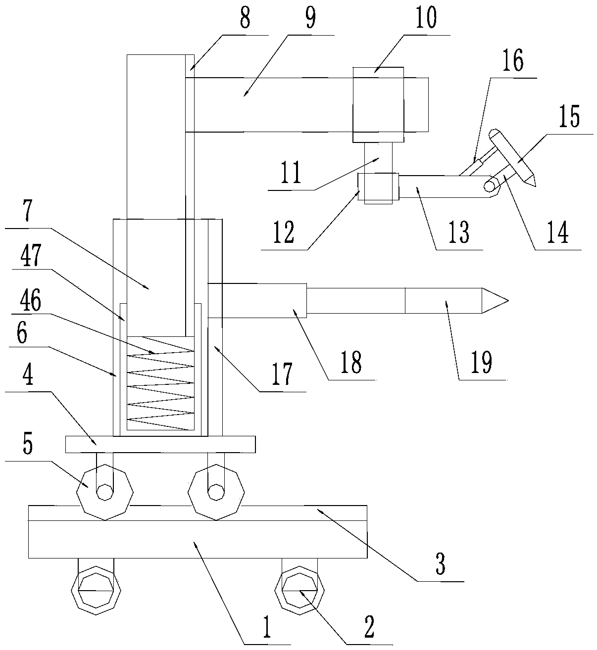
[0015] Such as figure 1 and figure 2 As shown, this specific embodiment adopts the following technical solutions: a clamping method for automobile welding, including a base 1, a universal wheel 2, a chute 3, a fixed seat 4, a pulley 5, an outer tube 6, and an inner tube 7 , the first slide rail 8, the first beam 9, the first jacket 10, the connecting rod 11, the second outer tube 12, the second beam 13, the rotating shaft 14, the main welding gun 15, the air pressure rod 16, the second slide rail 17, The third beam 18 and auxiliary welding gun 19; the lower surface of the base 1 is provided with several universal wheels 2, and the universal wheels 2 have a locking structure, which is used to lock the position of the universal wheels 2; the base 1 The upper surface of the upper surface is fixedly connected with a chute 3; the lower surface of the fixed seat 4 is provided with several pulleys 5, and the pulley 5 is matched with the chute 3 in clearance; the pulley 5 is arrange...


PUM


Abstract

The invention discloses a clamping method for automobile welding. According to the technical scheme, a workpiece is clamped on a placing block, the clamping method comprises the following steps that aheightening block extends to a proper position to enable the height of a lower pressing block to be higher than the position of an upper pressing block and to enable the lower pressing block to be incontact with the bottom surface of the workpiece, at the moment, a manipulator pneumatic rod is used for controlling a manipulator to release the workpiece, then a manipulator mounting seat goes backthe same way, a rotating rod rotates to a proper angle to enable the workpiece to be capable of avoiding the lower pressing block to move downwards, then the heightening block is retracted to the original height, a lifting rod rises to a proper height to be higher than the height of the workpiece, then the rotating rod rotates to a proper angle to enable the side part of the workpiece to be justpositioned below the upper pressing block, a pushing block is pushed by the clamping pneumatic rod, and then the workpiece is clamped through the upper pressing block. The clamping method has the advantages that the structure is reasonable and simple, the production cost is low, the installation is convenient, the multiple-degree-of-freedom limitation can be carried out on materials with differentsizes and different shapes so as to ensure that complete clamping of the material is achieved, and then the quality of a product obtained by welding can be ensured.

Description

Technical field: [0001] The invention relates to the technical field of automobile processing, in particular to a clamping method for automobile welding. The present invention is an application number: 2017106490262, application date: 2017.08.01, invention name: a divisional application of a welding device for automobile processing and manufacturing. Background technique: [0002] At present, the development of steel or other materials will put forward newer, higher and more requirements in many aspects such as welding technology and its process, consumables, equipment, automation, efficiency, cost, life, maintenance, and remanufacturing. Welding methods are developed complementary to each other under the impetus of the development of modern industry and science and technology. It can be predicted that with the continuous development of modern industry and science and technology, there will be new developments in welding technology and equipment. Therefore, welding fixture...

Claims


Application Information

Patent Timeline
Patent Type & Authority Applications(China)
IPC IPC(8): B23K37/02B23K37/04
CPCB23K37/02B23K37/0211B23K37/04B23K37/0443B23K2101/006
Inventor 汪思芳
Owner 汪思芳
Why Eureka
Try Eureka