
Grinding head device capable of precisely controlling sensing quantity

A precise and controller technology, applied in grinding drives, grinding heads, manufacturing tools, etc., can solve the problems of electric spindle burnout, increased cutting force, and inability to meet the strict requirements of casting shape and size consistency. , to achieve the effect of accurately ensuring the positioning accuracy of the clamping, accurately ensuring the consistency of the size, and being conducive to product quality control management.

Pending Publication Date: 2018-12-07
厦门达科塔机械有限公司
View PDF0 Cites 0 Cited by
  • Summary
  • Abstract
  • Description
  • Claims
  • Application Information

AI Technical Summary

Problems solved by technology

[0003] However, most of the existing grinding equipment on the market is equipped with non-floating grinding heads. If the riser and flash of the casting are large, this kind of hard grinding is easy to produce over-grinding and undergrinding.
When over-grinding, the cutting force of the grinding wheel will increase instantaneously, causing the electric spindle to be overloaded with current and burn out the electric spindle; when under-grinding, the dimensional consistency of the casting after grinding cannot be guaranteed, and secondary rework is required, which is difficult Automated finishing of large batches
[0004] The grinding head equipped with a small number of grinding equipment has a floating function, but the floating device adopts the scheme of radially installed springs, the floating angle cannot be accurately controlled, and the sensing value depends on the designer's experience and on-site debugging. Satisfy the stringent requirements of large-volume automated finishing for the consistency of casting dimensions

Method used


Image

  • Grinding head device capable of precisely controlling sensing quantity
  • Grinding head device capable of precisely controlling sensing quantity
  • Grinding head device capable of precisely controlling sensing quantity

Examples


Embodiment Construction

[0031] The present invention will be further described below in conjunction with the accompanying drawings and specific embodiments.

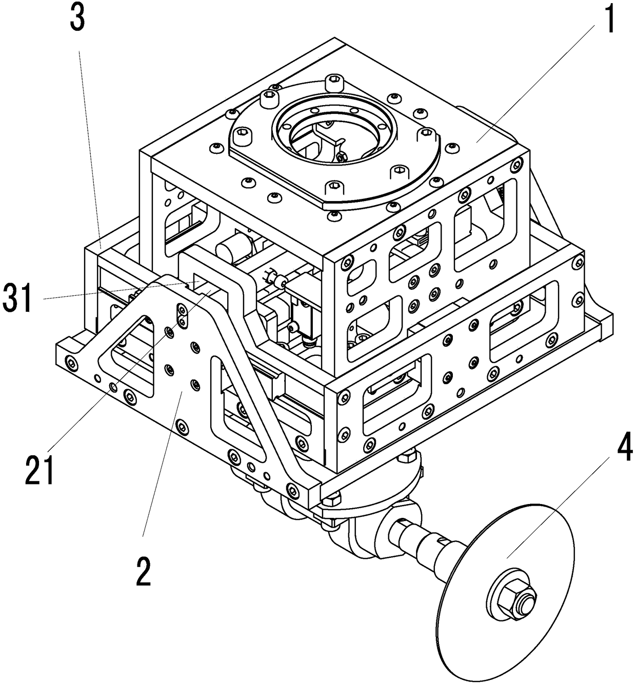
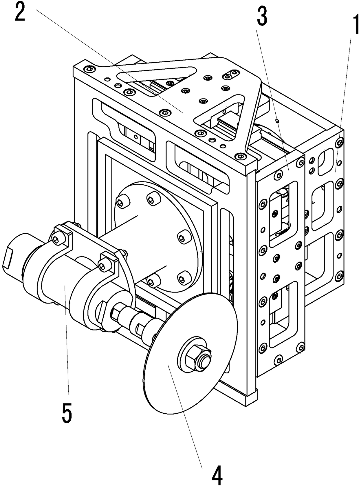
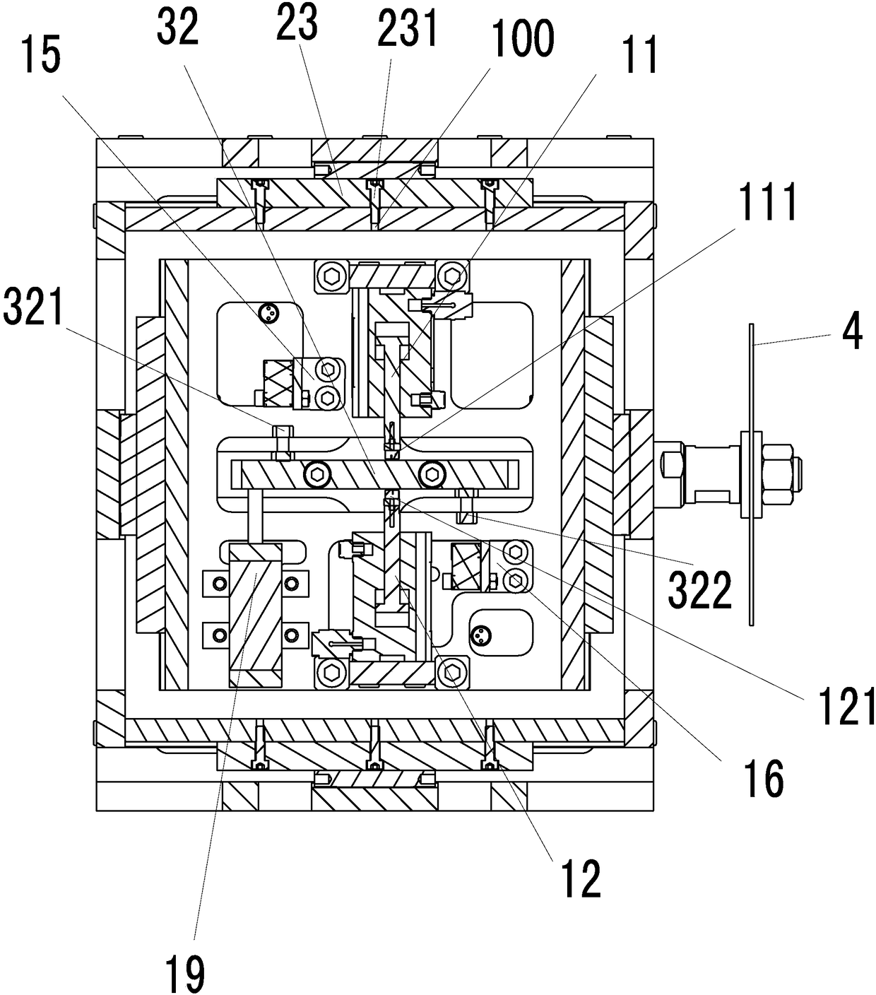
[0032] A grinding head device that precisely controls the amount of perception, refer to Figures 1 to 9 , comprising a housing frame 1, a moving bracket, and a controller; the housing bracket 1 and the moving bracket are respectively slidably connected along a first straight line direction and a second straight line direction; the first straight line is separated from the second straight line Set at a certain angle, in order to obtain the best working angle, the first straight line direction and the second straight line direction are perpendicular to each other;

[0033]The accommodating frame 1 is provided with a first drive assembly 11 and a second drive assembly 12 connected to the controller along the first linear direction, and the movement direction of the first drive assembly 11 and the second drive assembly 12 is opposite; The housing...


PUM


Abstract

The invention provides a grinding head device capable of precisely controlling a sensing quantity. The grinding head device comprises an accommodating frame, a movable bracket and a controller; the accommodating frame and the movable bracket are slidingly connected in a first straight direction and a second straight direction; the accommodating frame is provided with a first driving module and a second driving module, connected with the controller, in the first straight direction; and the accommodating frame is provided with a third driving module and a fourth driving module, connected with the controller, in the second straight direction. The grinding head device further comprises a first sensing module and a second sensing module. The grinding head device further comprises a polishing piece and an electric main shaft; the electric main shaft is connected between the surface, far from the accommodating frame, of the movable bracket and the polishing piece; the electric main shaft drives the movable bracket to move; and the controller controls the electric main shaft to stop rotating. The grinding head device can prevent the impact commission of the electric main shaft during polishing of castings to the greatest extent, improves the polishing quality, and effectively protects polishing equipment.

Description

technical field [0001] The invention relates to the field of floating grinding, in particular to a grinding head device that precisely controls the perceived amount. Background technique [0002] As advanced countries have developed towards Industry 4.0 (intelligent production), the goal of my country's Industry 3.0 (fully automated production) has not been fully realized, especially the front grinding process of the foundry industry. Due to the complex and irregular structure of the casting, the surfaces, holes and edges that need to be polished are distributed around the casting, making grinding difficult. At the current stage in our country, the front grinding process of castings mainly relies on manual grinding, and some factories have introduced a small number of grinding equipment. [0003] However, most of the existing grinding equipment on the market is equipped with a non-floating grinding head. If the riser and flash of the casting are large, this kind of hard gri...

Claims


Application Information

Patent Timeline
Patent Type & Authority Applications(China)
IPC IPC(8): B24B41/00B24B47/10
CPCB24B41/002B24B47/10
Inventor 陈成棋张满华张荣辉
Owner 厦门达科塔机械有限公司
Learn More