
Material touch signal generator

A signal generator, signal transmitter technology, applied in the direction of instruments, engine components, liquid level indicators, etc., can solve the problem of reducing the reliability and stability of the weight detection type material level measuring device, and the reliability and stability have not been Very good improvement, unsatisfactory effect and other problems, to achieve the effect of improving reliability and operation stability, simple structure, and improving measurement accuracy

Inactive Publication Date: 2010-09-22
BEIJING ARITIME INTELLIGENT CONTROL
View PDF7 Cites 0 Cited by
  • Summary
  • Abstract
  • Description
  • Claims
  • Application Information

AI Technical Summary

Problems solved by technology

However, the existing heavy hammer detection type material level measuring device generally has the moment when the heavy hammer touches the material. Due to the loss of tension of the steel wire rope, the vibration will cause the steel wire rope to jump out of the groove, causing faults such as disordered rope, rope jamming, broken rope and hammer drop, which greatly reduces The reliability and stability of the work of the heavy hammer detection type material level measuring device
Although some heavy hammer detection type material level measuring devices have made some improvements to address these faults, the effect is not satisfactory, and the reliability and stability have not been well improved.
At present, there is no universal device that can be applied to various heavy hammer detection type material level measuring instruments, so that various heavy hammer detection type material level measurement instruments can work stably and reliably, and is also suitable for various harsh environments. environment of

Method used


Image

  • Material touch signal generator
  • Material touch signal generator
  • Material touch signal generator

Examples


Embodiment Construction

[0020] The present invention will be further described in detail below in conjunction with the accompanying drawings.

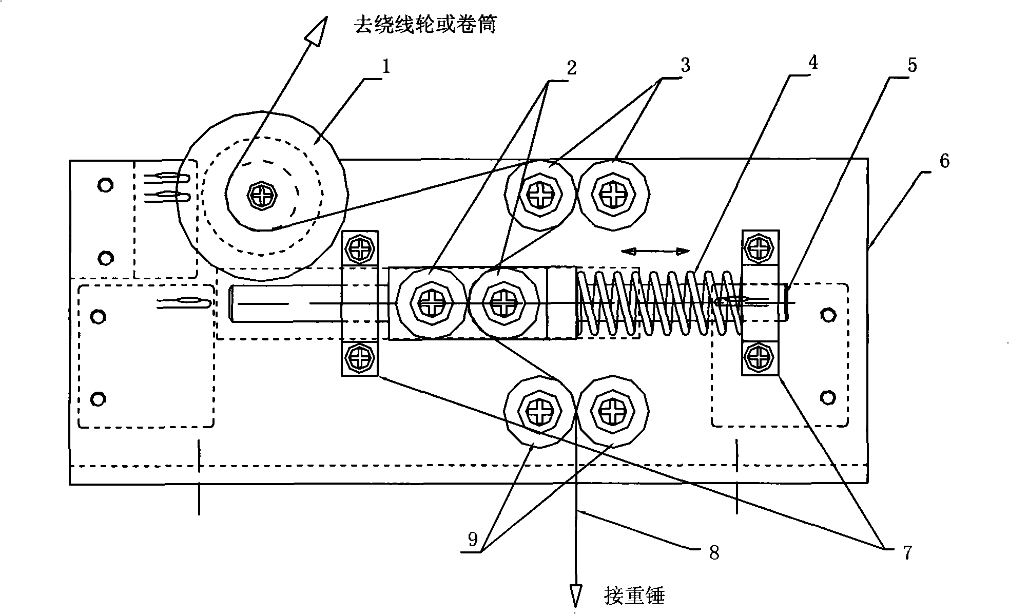
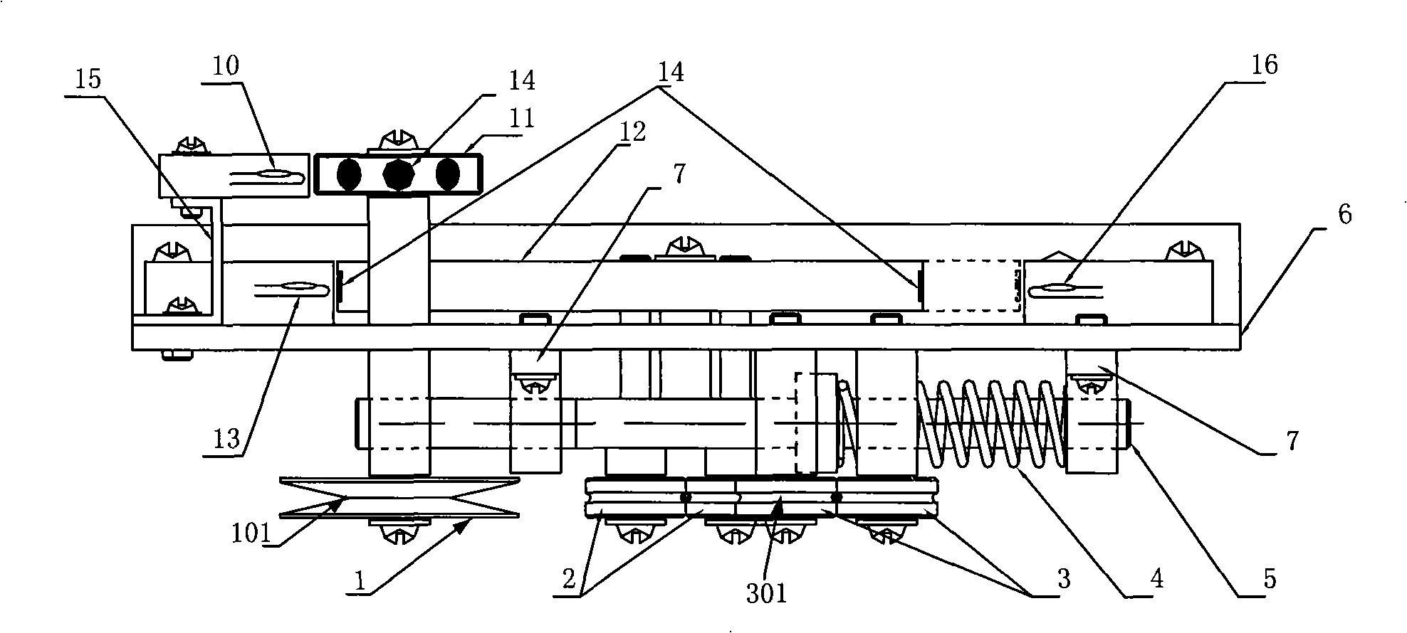
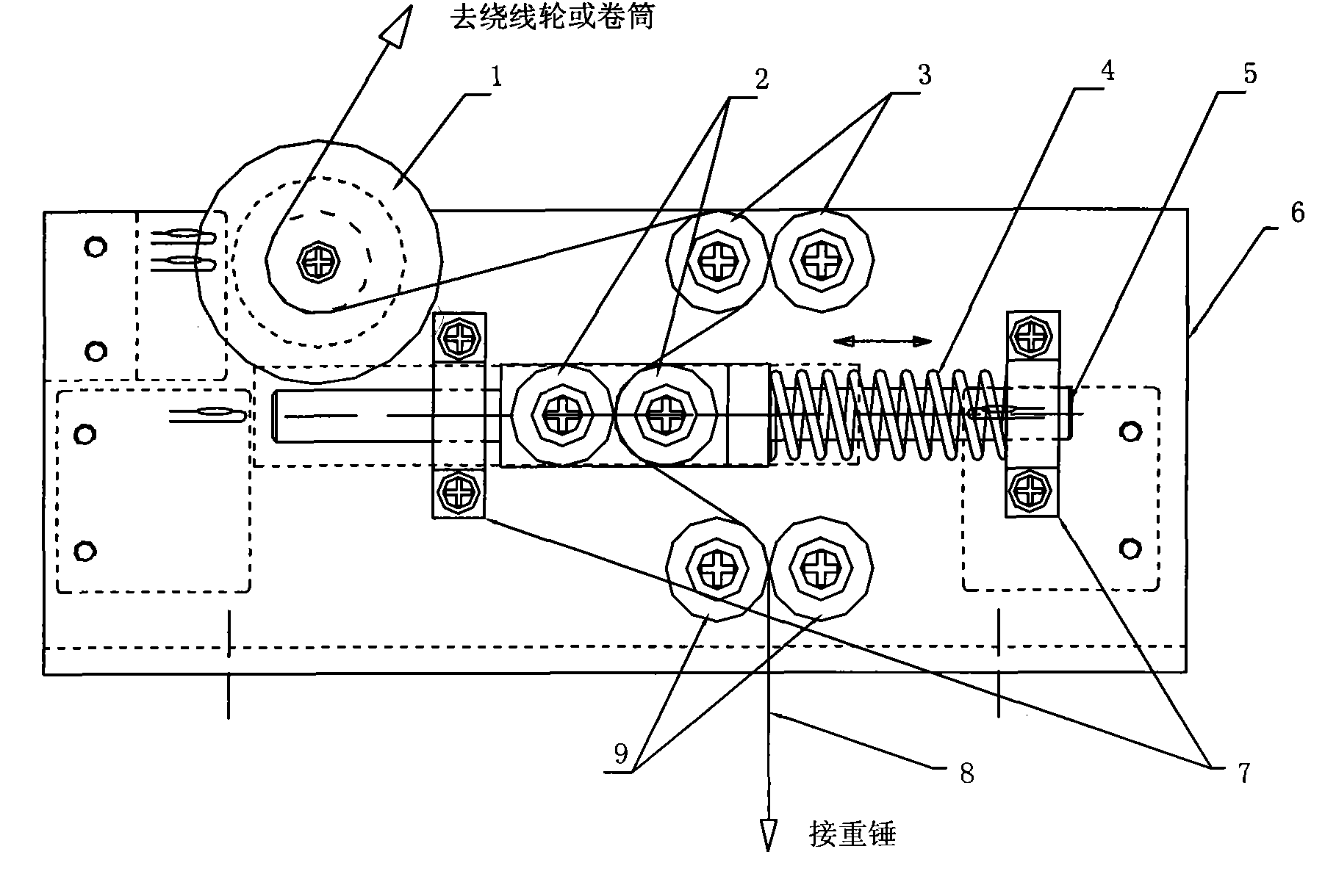
[0021] Such as figure 1 , figure 2 As shown, the contact signal generator provided by the present invention includes: measuring shaft wheel 1, elastic shaft wheel 2, upper guide shaft wheel 3, spring 4, contact rod 5, bracket 6, contact rod support 7, steel wire rope 8, Lower guide shaft wheel 9, material level pulse transmitter 10, pulse wheel 11, contact material block 12, contact material signal transmitter 13, magnetic steel 14, pulse signal transmitter bracket 15, buried hammer signal transmitter 16. The support 6 is a plate-like structure, a horizontal measuring shaft at the front end of the support 6 is perpendicular to the plane of the support 6, and the two ends of the measuring shaft are provided with a measuring shaft wheel 1 and a pulse wheel 11, which are respectively located on both sides of the support 6 and connected to the pulse wheel. 11 ...


PUM


Abstract

The invention discloses a material touch signal generator, comprising a measuring arbor wheel, an elastic arbor wheel, an upper guiding arbor wheel, a spring, a material touch bar, magnetic steel, a bracket, a material touch bar bracket, a steel rope, a lower guiding arbor wheel, and the like. One end of the steel rope is circled around a wire wheel or a wound roll through the upper guiding arborwheel and the measuring arbor wheel, and the other end is connected with a heavy bob at last through the elastic arbor wheel and the lower guiding arbor wheel. With the effect of the heavy bob, the material touch bar overcomes the acting force of the spring to move; when the front end of a material touch block is close to the material touch signal generator, the material touch signal generator sends material touch signal to a control unit; when the back end of the material touch block is close to a covered bob signal generator, the covered bob signal generator sends covered bob fault signal to the control unit. The generator has simple structure, integrated design and unitization use, and can be conveniently applied to various heavy bob detection type level gauging devices that can guarantee long-term, reliable and stable operation in very bad conditions.

Description

technical field [0001] The invention belongs to the field of automatic measurement, and in particular relates to a contact signal generator. Background technique [0002] At present, there are many kinds of devices and instruments used for silo material level measurement, with different precision and accuracy. Non-contact material level measuring instruments such as radar and ultrasonic can measure almost all media due to their own characteristics, and the operation It is simple, easy to debug, and has high measurement accuracy, but the measurement data is unreliable when used in high-temperature, high-density dust environments. With the improvement of automation level, the requirements for the accuracy, accuracy, reliability and stability of material level measurement are getting higher and higher. However, the existing heavy hammer detection type material level measuring device generally has the moment when the heavy hammer touches the material. Due to the loss of tension...

Claims


Application Information

Patent Timeline
Patent Type & Authority Patents(China)
IPC IPC(8): G01F23/284
Inventor 高增雪金亮邹凤欣杨溪林
Owner BEIJING ARITIME INTELLIGENT CONTROL
Learn More