Power reactive power compensation capacitance detection and AC contactor protection circuit
What is Al technical title?
Al technical title is built by PatSnap Al team. It summarizes the technical point description of the patent document.
A technology for AC contactors and compensation capacitors, applied in reactive power compensation, AC network circuits, emergency protection circuit devices for limiting overcurrent/overvoltage, etc., can solve arc burning AC contactors, fires, and circuit damage Components and other issues
Active Publication Date: 2021-03-23
LUAN TONGXIN CHANGNENG ELECTRONICS TECH CO LTD
View PDF3 Cites 0 Cited by
Summary
Abstract
Description
Claims
Application Information
AI Technical Summary
This helps you quickly interpret patents by identifying the three key elements:
Problems solved by technology
Method used
Benefits of technology
Problems solved by technology
[0004] During the use of traditional reactive compensation capacitance detection, because the circuit does not have the effect of controlling the normally open contact of the AC contactor, the arc generated by the instantaneous high current charging will burn the AC contactor, and even destroy the circuit components. , serious cause fire, endanger people's life and property safety
Method used
Image
Click on the blue label to locate the original text in one second.
Reading with bidirectional positioning of images and text.
Examples
Embodiment 1
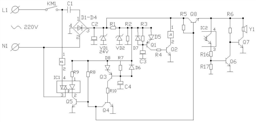
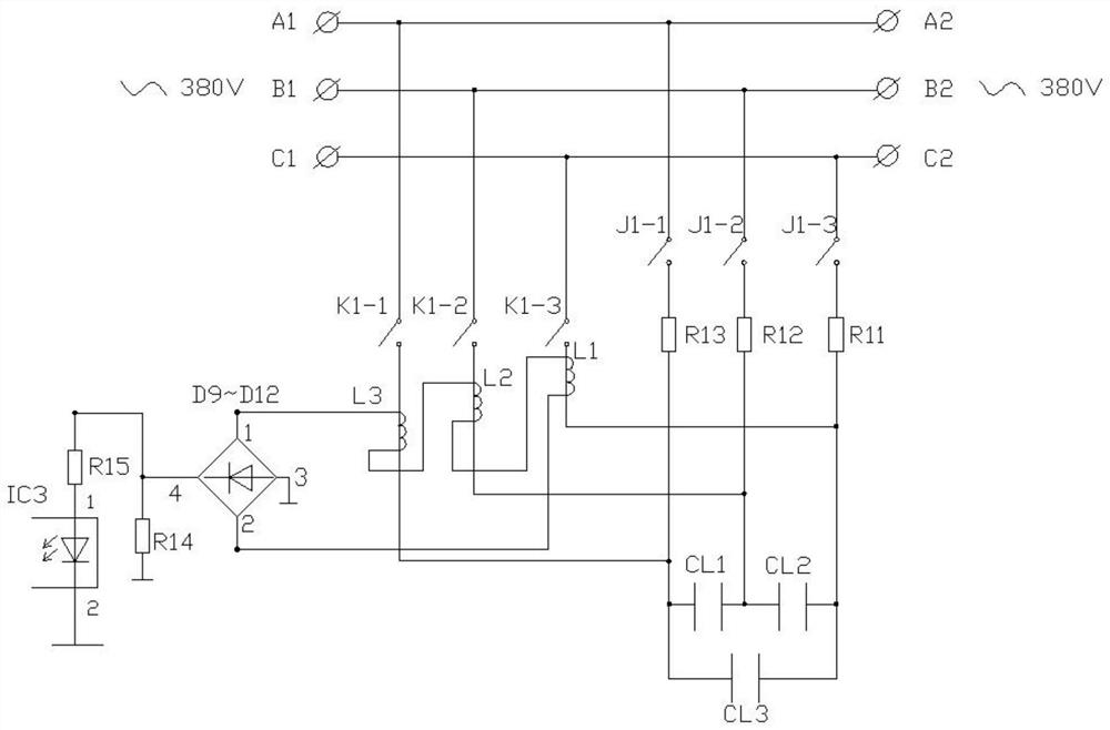
[0016] see Figure 1-2 As shown, the power reactive power compensation capacitance detection and AC contactor protection circuit includes neutral line L1, live line N1, switch KM1, bridge rectifier diodes D1~D4, bridge rectifier diodes D9~D12, optical coupler IC1, optical Inductive coupler IC2, optical coupler IC3, Zener diode VD1, Zener diode VD2, Transistor Q1, Transistor Q2, Transistor Q3, Transistor Q4, Transistor Q5, Transistor Q6, Transistor Q7, Diode D5, Diode D6, Diode D7 , diode D8, relay J1, relay normally closed contact JI-1, relay normally closed contact JI-2, relay normally closed contact JI-3, AC contactor K1, AC contactor normally closed contact K1-1, AC contactor normally closed contact K1-2, AC contactor normally closed contact K1-3, reactive compensation capacitor CL1, reactive compensation capacitor CL2, reactive compensation capacitor CL3, capacitor C1, capacitor C2, capacitor C3, capacitor C4, resistor R1, resistor R2, resistor R3, resistor R4, resistor R...
PUM
Abstract
The invention discloses a power reactive compensation capacitor detection and AC contactor protection circuit, comprising a neutral line L1, a live line N1, a switch KM1, bridge rectifying diodes D1 to D4, bridge rectifying diodes D9 to D12, optical inductive coupler IC1 to I3, Zener Diodes VD1 To VD2, transistors Q1 to Q7, Diodes D5 to D8, a relay J1, a relay normally close contact JI-1, a Relaynormally closed contact JI-2, A Relay normally closed contact JI-3, an AC contactor K1, AC contactor normally closed contact K1-1, an AC contactor normally closed contact K1-2, a Normally closed contact K1-2, an AC contactor normally closed contact K1-3, Reactive Compensation Capacitors CL1 to CL3, Capacitors C1 to C4, Resistor R1 to R15, and a buzzer Y1; By setting reactive power compensation capacitor detection and AC contactor protection circuit, the reactive power compensation capacitor on the three-phase voltage works in parallel with the three-phase voltage, so that the power equipmentused can obtain the capacitor compensation power, and at the same time, When the AC contactor is turned on instantaneously, the reactive current compensation capacitor is turned on, and the arc generated by the high current charging is instantaneously prevented from burning the AC contactor.
Description
technical field [0001] The invention relates to the field of electronic equipment, in particular to electric reactive power compensation capacitance detection and AC contactor protection circuits. Background technique [0002] Capacitors are widely used in many terminal electronic devices, for example, AC contacts for touch control on the display screen of terminal devices. [0003] The working principle of the AC contactor is to use the electromagnetic force to cooperate with the spring force to realize the connection and disconnection of the contacts. The AC contactor has two working states: de-energized state (release state) and energized state (action state). When the attraction coil is energized, the static iron core generates electromagnetic attraction force, the armature is attracted, and the connecting rod connected with the armature drives the contact to move, so that the normally closed contact breaker contactor is in an energized state; when the attraction coil i...
Claims
Application Information
Patent Timeline
Application Date:The date an application was filed.
Publication Date:The date a patent or application was officially published.
First Publication Date:The earliest publication date of a patent with the same application number.
Issue Date:Publication date of the patent grant document.
PCT Entry Date:The Entry date of PCT National Phase.
Estimated Expiry Date:The statutory expiry date of a patent right according to the Patent Law, and it is the longest term of protection that the patent right can achieve without the termination of the patent right due to other reasons(Term extension factor has been taken into account ).
Invalid Date:Actual expiry date is based on effective date or publication date of legal transaction data of invalid patent.
Patent Type & Authority Patents(China)
IPC IPC(8): H02J3/18H02H9/08
CPCH02H9/08H02J3/1842Y02E40/30
Inventor 刘举柱
Owner LUAN TONGXIN CHANGNENG ELECTRONICS TECH CO LTD