
Mounting and adjusting tool applicable to fork plunger type steering engine and use method thereof

A technology of installation adjustment and adjustment work, which is applied in the direction of hand-held tools, manufacturing tools, workpiece clamping devices, etc., can solve the problems of difficulty in ensuring the accuracy and reliability of equipment installation, no mention of technical design, and low accuracy. Achieve the effect of ensuring the accuracy and reliability of equipment installation, strong adjustability and multi-directional, and improving accuracy

Inactive Publication Date: 2018-12-07
WUHAN MARINE MACHINERY PLANT
View PDF5 Cites 2 Cited by
  • Summary
  • Abstract
  • Description
  • Claims
  • Application Information

AI Technical Summary

Problems solved by technology

Although this design can achieve the purpose of increasing the number of rudder cylinders, and can increase the torque of the steering gear by multiples, it cannot ensure that each hydraulic cylinder is installed from the reference point (the center of the sample punching circle) to the tiller (that is, the rudder shaft) The distances between the centers are all equal, and there is no mention of the relevant technical design, resulting in a low accuracy of the distance between the center of the cylinder-like punching hole and the center of the rudder shaft in the middle of the rudder mechanism, making it difficult to ensure the accuracy and reliability of equipment installation sex

Method used


Image

  • Mounting and adjusting tool applicable to fork plunger type steering engine and use method thereof
  • Mounting and adjusting tool applicable to fork plunger type steering engine and use method thereof
  • Mounting and adjusting tool applicable to fork plunger type steering engine and use method thereof

Examples


Embodiment 1

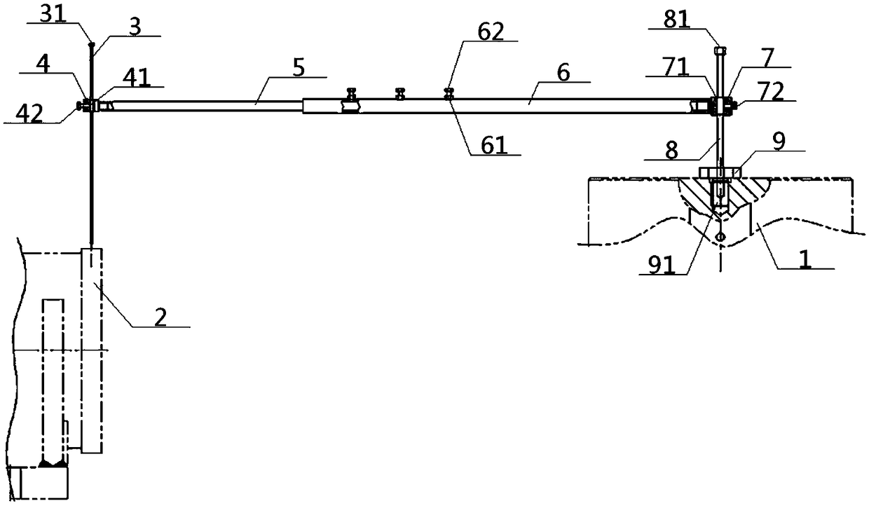
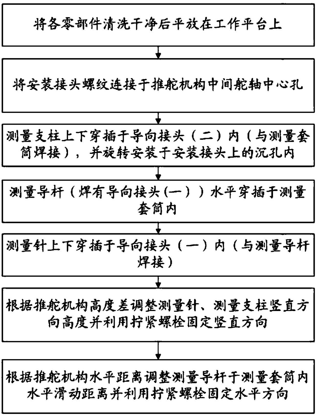
[0056] see Figure 1 to Figure 5 , a kind of installation and adjustment tooling suitable for a fork plunger type steering gear; the installation and adjustment tooling includes a measuring needle 3, a guide joint 1 4, a measuring guide rod 5, a measuring sleeve 6, a guide joint 2 7, a measuring pillar 8 and The joint 9 is installed, and the inside of the guide joint 4 is provided with a needle cavity 41 for the measuring needle 3 to pass through. The right end of the guide joint 4 is connected with the left end of the measurement guide rod 5, and the right end of the measurement guide rod 5 extends To the inside of the measuring sleeve 6, the part of the measuring guide rod 5 located in the measuring sleeve 6 is slidably fitted with the inner cavity of the measuring sleeve 6, the right end of the measuring sleeve 6 is connected with the left end of the guide joint 2 7, and the guide The inside of the joint 2 7 is provided with a column cavity 71 for the measuring pillar 8 to ...

Embodiment 2

[0066] Basic content is the same as embodiment 1, the difference is:

[0067] The fixing of the measuring needle 3 and the measuring pillar 8 refers to: the needle fixing bolt 42 is screwed inward along the through-needle cavity 41 to suppress the measuring needle 3 in the through-needle cavity 41 to realize the fixing of the measuring needle 3 The column fixing bolt 72 is screwed inward along the column cavity 71 to press the measuring pillar 8 in the column cavity 71 to fix the measuring column 8 . The fixing of the measuring guide rod 5 refers to: on the side wall of the measuring sleeve 6, the tightening bolt 62 is screwed inward along the tightening nut 61, so that the tightening bolt 62 presses the measuring guide rod in the measuring sleeve 6 5. Realize the fixing of the measuring guide rod 5 .

Embodiment 3

[0069] Basic content is the same as embodiment 1, the difference is:

[0070] After the measuring needle 3, the measuring pillar 8, and the measuring guide rod 5 are all fixed, the distance between the center 2 of an oil cylinder-like punching hole and the center of the rudder shaft 1 in the middle of the rudder mechanism can be measured, and then, the same method is used to measure Get the distance between the center 2 of the punching hole of the remaining three oil cylinder samples and the center of the rudder shaft 1 of the rudder mechanism, then compare the measured four actual distance values ​​with the theoretical values, and then adjust the on-site installation in real time according to the comparison results, so as to Ensure that the installation accuracy of the rudder mechanism meets the requirements.


PUM


Abstract

The invention discloses a mounting and adjusting tool applicable to a fork plunger type steering engine. The mounting and adjusting tool comprises a measuring pin, a guide sub I, a measuring guide rod, a measuring sleeve, a guide sub II, a measuring strut and a mounting joint; the measuring pin slides up and down along the interior of the guide sub I; the guide sub I is connected with the left endof the measuring guide rod; the right end of the measuring guide rod extends into the measuring sleeve for sliding fit; the measuring sleeve is connected with the guide sub II; and the bottom end ofthe measuring strut sliding up and down along the interior of the guide sub II is vertically connected with the mounting joint. During application, the heights of two different points are adjusted with the measuring pin and the measuring strut, and the distance between the two different points are adjusted by relative sliding of the measuring guide rod and the measuring sleeve, so that the actualdistance between a middle rudder shaft an oil cylinder is measured, and site installation is adjusted in real time according to an actual distance value and a theoretical value. The precision of the distance between the circle center of a punching point eye of the oil cylinder and the center of the middle rudder shaft of a rudder pushing mechanism can be improved, and equipment installation veracity and reliability can be guaranteed.

Description

technical field [0001] The present invention relates to a measurement and adjustment tool, in particular to a tooling suitable for installation and adjustment of a fork plunger type steering gear and its use method, and is particularly suitable for increasing the distance between the center of the center of the center of the center of the rudder shaft of the rudder pushing mechanism and the center of the center of the center of the rudder pushing the rudder. The accuracy to ensure the accuracy and reliability of equipment installation. Background technique [0002] In the large-scale fork plunger hydraulic steering gear, the rudder pushing mechanism, as the actuator of the hull steering system, is directly connected with the rudder shaft, and is used to drive the rudder shaft to drive the rudder blades, so as to realize the turning of the hull and maintain the course. Therefore, the accuracy of the installation of the rudder mechanism must be guaranteed, otherwise, once the ...

Claims


Application Information

Patent Timeline
Patent Type & Authority Applications(China)
IPC IPC(8): B25B11/00B25B27/00
CPCB25B11/00B25B27/00
Inventor 韩晓君武江勇易兆红金彩张志清朱国斌
Owner WUHAN MARINE MACHINERY PLANT
Learn More