Eureka AIR delivers breakthrough ideas for toughest innovation challenges, trusted by R&D personnel around the world.

Turnover type pedal boarding device

A flip-top, pedal technology, applied in the direction of the fuselage, aircraft maintenance, aircraft parts, etc., can solve the problems of easy swing of the ladder, large installation space, limited use area, etc., to achieve convenient maintenance and pilots getting on and off the plane, stable and reliable Support structure, the effect of not taking up space

Inactive Publication Date: 2018-12-07
JIANGXI HONGDU AVIATION IND GRP
View PDF5 Cites 0 Cited by
  • Summary
  • Abstract
  • Description
  • Claims
  • Application Information

AI Technical Summary

Problems solved by technology

[0002] The ground crew maintains the aircraft and the pilots need to use boarding ladders when they get on and off the plane. The boarding ladders are divided into conventional boarding ladders and random boarding ladders. Divided into extended type and internal embedded type, such as the extended "U-shaped" pole boarding ladder and the internal embedded boarding foot socket. The externally extended rod boarding ladder has a simple structure, but affects the aerodynamic characteristics of the aircraft. The type boarding footwell is limited by the space, so it is not convenient for the pilot to step on it
Patent No. CN203127148U discloses a pedal device, which provides a stable support structure for ground crews to ensure that ground crews can work safely; With the ground crew and the difficult and complicated field environment, conventional boarding ladders cannot meet the requirements of pilots. This boarding ladder has four ladders that require a large installation space, the structure is complex, and the first and second ladders are prone to accidents due to suspension Wobble, not conducive to ground crew and pilots stepping on and off the plane

Method used


Image

  • Turnover type pedal boarding device
  • Turnover type pedal boarding device
  • Turnover type pedal boarding device

Examples


Embodiment Construction

[0021] In order to make the technical means, creative features, goals and effects achieved by the present invention easy to understand, the present invention will be further described below in conjunction with specific illustrations.

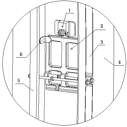
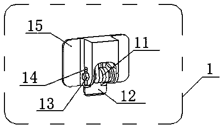
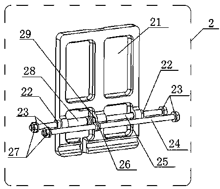
[0022] see Figure 1 ~ Figure 4 A flip-type pedal boarding device, comprising a lock mechanism 1, a pedal mechanism 2, a first fuselage frame 3, a skin 4, a second fuselage frame 5 and 6 angle pieces, wherein the first fuselage The body frame 3 and the second fuselage frame 5 are positioned and fixed on the fuselage by the aircraft assembly mounting frame, and the skin 4 is riveted on the first fuselage frame 3 and the second fuselage frame 5 by rivets, and is used for the pedal The angle piece 6 for limiting the position of the plate 21 is riveted on the second fuselage frame 5, the lock mechanism 1 is riveted on the skin 4, and the pedal mechanism 2 is arranged on the fuselage below the lock mechanism 1. The specific structure as follows:

...


PUM


Abstract

A turnover type pedal boarding device comprises a fastener mechanism, a pedal plate mechanism, a first airplane body frame, a skin and a second airplane body frame, wherein the first airplane body frame and the second airplane body frame are positioned and fixed to an airplane body through an airplane assembling and mounting fixture; the skin is riveted on the first airplane body frame and the second airplane body frame; the fastener mechanism is riveted on the skin; the pedal plate mechanism is arranged at the part, positioned under the fastener mechanism, of the airplane body; a fastener spring is arranged on the fastener mechanism; a pedal plate spring is arranged on the pedal plate mechanism; by using an elastic force of the spring, turnover and folding are realized; the turnover typepedal boarding device is opened at any time, is easy to retract and expand, does not occupy the space, provides a stable and reliable supporting structure without affecting appearance requirements ofan airplane on overall aerodynamic characteristics, is convenient for ground crew to maintain the airplane and is convenient for pilots to get on and off the airplane; and the applicability is high.

Description

technical field [0001] The invention relates to the technical field of aircraft structures, in particular to a flip-type pedal boarding device. Background technique [0002] The ground crew maintains the aircraft and the pilots need to use boarding ladders when they get on and off the plane. The boarding ladders are divided into conventional boarding ladders and random boarding ladders. Divided into extended type and internal embedded type, such as the extended "U-shaped" pole boarding ladder and the internal embedded boarding foot socket. The externally extended rod boarding ladder has a simple structure, but affects the aerodynamic characteristics of the aircraft. The type boarding foot well is limited by space, which is not convenient for the pilot to step on. Patent No. CN203127148U discloses a pedal device, which provides a stable support structure for ground crews to ensure that ground crews can work safely; With the ground crew and the difficult and complicated fiel...

Claims


Application Information

Patent Timeline
Patent Type & Authority Applications(China)
IPC IPC(8): B64C1/24B64F5/40
CPCB64C1/24B64F5/40
Inventor 张勇王建华王强袁平湘余志明陈里根林振华许小妹黄颖鄢仁浙邹俊磊
Owner JIANGXI HONGDU AVIATION IND GRP
Why Eureka
Eureka Blog
Learn More