Cleaning bar limiting device convenient to clean

A technology of a limit device and fluent strips, which is applied in the field of fluent strips

Inactive Publication Date: 2018-12-07
湖州吴兴双德输送机械有限公司
7 Cites 3 Cited by

AI-Extracted Technical Summary

Problems solved by technology

[0004] Aiming at the deficiencies of the prior art, the present invention provides an easy-to-c...

Abstract

The invention discloses a cleaning bar limiting device convenient to clean. The device comprises a base plate; one side of the top of the base plate is fixedly connected with a first support plate; afirst limiting clamping groove is formed in the first support plate; a first limiting slide block is rotationally connected into the first limiting clamping groove; one side of the surface of the first limiting slide block is fixedly connected with a first rotating shaft; the first rotating shaft penetrates through the first support plate, and extends to the external of the first support plate; the end, extending to the external of the first support plate, of the first rotating shaft is fixedly connected with a brush; a second rotating shaft is rotationally connected into the first support plate; the surface of the second rotating shaft is fixedly connected with a turntable; the surface of the turntable is fixedly connected with a first fixed shaft; the surface of the first fixed shaft isrotationally connected with a first pallet; the end, far from the first fixed shaft, of the first pallet is engaged with a ratchet; and the device relates to the technical field of cleaning bars. Thecleaning bar limiting device convenient to clean achieves the purposes of effective cleaning and limiting.

Application Domain

Cleaning

Technology Topic

EngineeringPallet

Image

  • Cleaning bar limiting device convenient to clean
  • Cleaning bar limiting device convenient to clean
  • Cleaning bar limiting device convenient to clean

Examples

  • Experimental program(1)

Example Embodiment

[0019] The technical solutions in the embodiments of the present invention will be clearly and completely described below in conjunction with the accompanying drawings in the embodiments of the present invention. Obviously, the described embodiments are only a part of the embodiments of the present invention, rather than all the embodiments. Based on the embodiments of the present invention, all other embodiments obtained by those of ordinary skill in the art without creative work shall fall within the protection scope of the present invention.
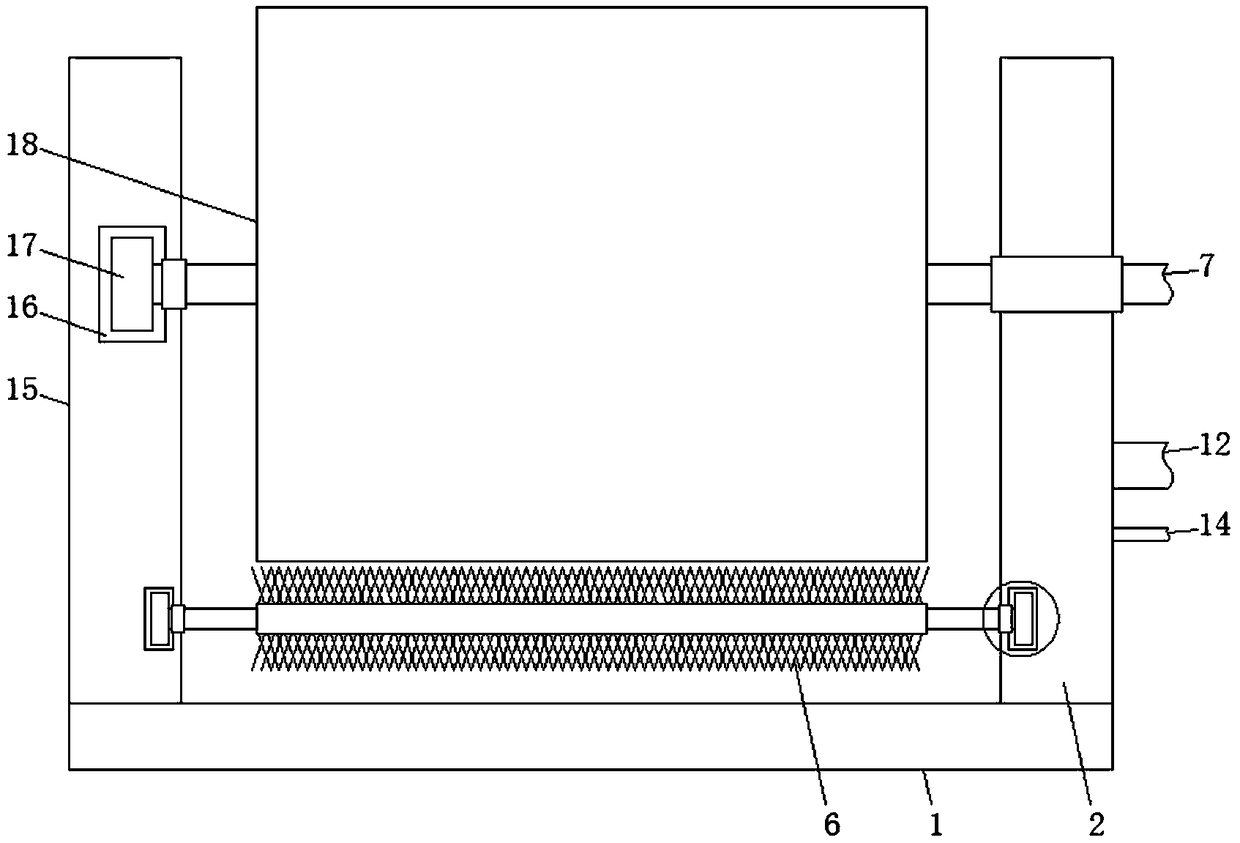
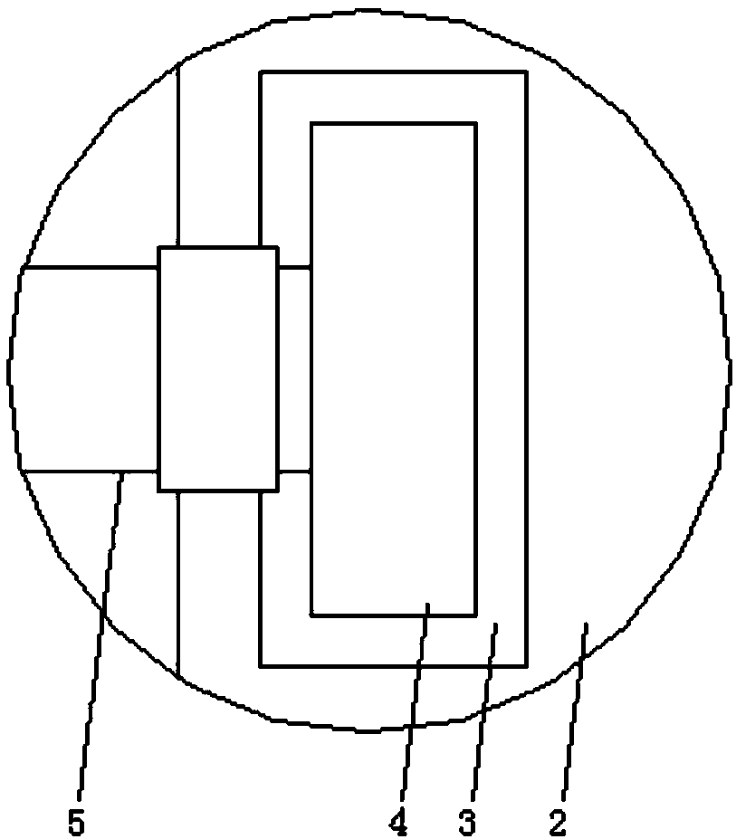
[0020] See Figure 1-3 , The present invention provides a technical solution: a fluent strip limiting device that is easy to clean, comprising a bottom plate 1, a first support plate 2 is fixedly connected to one side of the top of the bottom plate 1, and a first support plate 2 is provided inside the first support plate 2. The limit card slot 3, the inside of the first limit card slot 3 is rotatably connected with a first limit slider 4, one side of the surface of the first limit slider 4 is fixedly connected with a first rotating shaft 5, and the first rotating shaft 5 penetrates The first supporting plate 2 extends to the outside of the first supporting plate 2, the end of the first rotating shaft 5 extending to the outside of the first supporting plate 2 is fixedly connected with a brush 6, and the inside of the first supporting plate 2 is rotatably connected with a second rotating shaft 7. A turntable 8 is fixedly connected to the surface of the second rotating shaft 7, a first fixed shaft 9 is fixedly connected to the surface of the turntable 8, a first pawl 10 is rotatably connected to the surface of the first fixed shaft 9, and the first pawl 10 is far away from the One end of a fixed shaft 9 is engaged and connected with a ratchet wheel 11, the center of the ratchet wheel 11 is rotatably connected with a second fixed shaft 12, and the end of the second fixed shaft 12 away from the ratchet wheel 11 is fixedly connected to one side of the surface of the first support plate 2. The surface of the second pawl 13 is engaged and connected with the second pawl 13, the center of the second pawl 13 is rotatably connected to the third fixed shaft 14, the end of the third fixed shaft 14 away from the second pawl 13 and the side of the surface of the first support plate 2 Fixed connection. A second support plate 15 is fixedly connected to one side of the top of the bottom plate 1. A second limiting card slot 16 is opened inside the second supporting plate 15. A second limiting slider 17 is rotatably connected to the inside of the second limiting slot 16, and one side of the surface of the second limiting slider 17 is fixedly connected to the end of the second rotating shaft 7 away from the turntable 8. A roller 18 is fixedly connected between the surface of the second rotating shaft 7 and the side of the surface of the second supporting plate 15 and the side of the surface of the first supporting plate 2.
[0021] When in use, the object is pushed to the surface of the roller 18, the roller 18 drives the second rotating shaft 7 to rotate, the second rotating shaft 7 drives the second limiting slider 17 to rotate relative to the second limiting slot 16, and the second rotating shaft 7 drives the turntable 8 When rotating, the turntable 8 drives the first pawl 10 to rotate through the first fixed shaft 9, the first pawl 10 drives the ratchet wheel 11 to rotate relative to the second fixed shaft 12, and the ratchet wheel 11 drives the second pawl 13 to rotate relative to the third fixed shaft 14. The roller 18 drives the brush 6 to rotate, and the brush 6 drives the first limiting slider 4 to rotate relative to the first limiting slot 3 through the first rotating shaft 5.
[0022] It should be noted that in this article, relational terms such as first and second are only used to distinguish one entity or operation from another entity or operation, and do not necessarily require or imply one of these entities or operations. There is any such actual relationship or order between. Moreover, the terms "include", "include" or any other variants thereof are intended to cover non-exclusive inclusion, so that a process, method, article, or device that includes a series of elements includes not only those elements, but also includes Other elements of, or also include elements inherent to this process, method, article or equipment. Without more restrictions. The sentence "including an element defined by ... does not exclude the existence of other identical elements in the process, method, article, or equipment including the element."
[0023] Although the embodiments of the present invention have been shown and described, those of ordinary skill in the art can understand that various changes, modifications, and substitutions can be made to these embodiments without departing from the principle and spirit of the present invention. And variations, the scope of the present invention is defined by the appended claims and their equivalents.

PUM

no PUM

Description & Claims & Application Information

We can also present the details of the Description, Claims and Application information to help users get a comprehensive understanding of the technical details of the patent, such as background art, summary of invention, brief description of drawings, description of embodiments, and other original content. On the other hand, users can also determine the specific scope of protection of the technology through the list of claims; as well as understand the changes in the life cycle of the technology with the presentation of the patent timeline. Login to view more.
Why Eureka
Try Eureka