
Conveying assembly and automatic feeding device

A technology for automatic feeding and conveying materials, which is applied in the direction of conveyor objects, transportation and packaging, etc., and can solve problems such as not in place, easy to jam materials, etc.

Inactive Publication Date: 2018-12-07
TCL KING ELECTRICAL APPLIANCES HUIZHOU
View PDF6 Cites 7 Cited by
  • Summary
  • Abstract
  • Description
  • Claims
  • Application Information

AI Technical Summary

Problems solved by technology

[0003] The main purpose of the present invention is to provide a conveying assembly and an automatic feeding device, aiming to solve the problems of easy jamming and insufficient feeding during the feeding process of the automatic feeding mechanism

Method used


Image

  • Conveying assembly and automatic feeding device
  • Conveying assembly and automatic feeding device

Examples


Embodiment Construction

[0021] The following will clearly and completely describe the technical solutions in the embodiments of the present invention with reference to the accompanying drawings in the embodiments of the present invention. Obviously, the described embodiments are only part of the embodiments of the present invention, not all of them. Based on the embodiments of the present invention, all other embodiments obtained by persons of ordinary skill in the art without creative efforts fall within the protection scope of the present invention.

[0022] It should be noted that all directional indications (such as up, down, left, right, front, back...) in the embodiments of the present invention are only used to explain the relationship between the components in a certain posture (as shown in the accompanying drawings). Relative positional relationship, movement conditions, etc., if the specific posture changes, the directional indication will also change accordingly.

[0023] In addition, in t...


PUM


Abstract

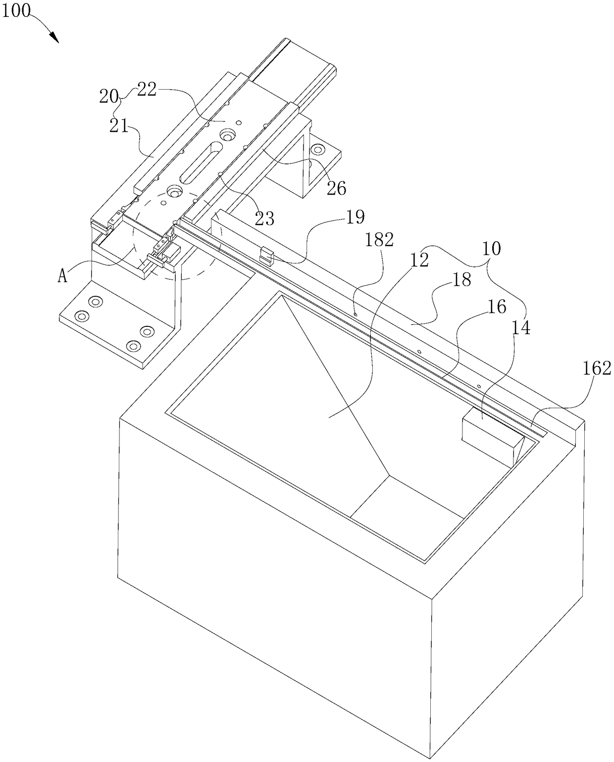
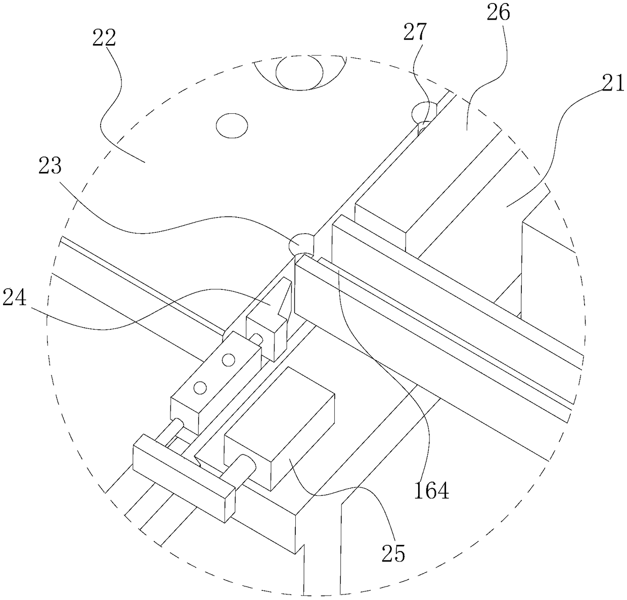
The invention discloses a conveying assembly and an automatic feeding device. The conveying assembly is used for conveying materials and comprises a material bin, a lifting feeding mechanism and a linear vibrator. The material bin is used for holding materials. The lifting feeding mechanism is used for conveying the materials in the material bin to the linear vibrator. The linear vibrator is arranged on the side wall of the material bin. The upper surface of the linear vibrator is provided with a clamping groove extending in the length direction of the linear vibrator. The clamping groove is used for clamping materials. The linear vibrator drives the materials to move to the output end of the clamping groove in the length direction. A baffle is arranged on the side, away from the materialbin, of the linear vibrator. The baffle is provided with a blowing hole used for being connected with a blowing mechanism, so that materials which are not clamped into the clamping groove are blown into the material bin through the blowing mechanism. In the technical scheme, the blowing mechanism can be installed at the blowing hole, the materials which are on the linear vibrator and are not stably clamped in the clamping groove are blown into the material bin, and the problems of material clamping and not-in-place feeding are avoided in the feeding process.

Description

technical field [0001] The invention relates to the technical field of automatic feeding, in particular to a conveying component and an automatic feeding device. Background technique [0002] In the related art, the backboard of the TV needs to be installed with screws. In order to improve the installation efficiency of the TV backplane, an automatic feeder is used to transport materials to replace manual work. However, during the feeding process of the automatic feeding mechanism, the problems of material jamming and insufficient feeding are prone to occur. Contents of the invention [0003] The main purpose of the present invention is to provide a conveying assembly and an automatic feeding device, aiming to solve the problems of easy material jamming and insufficient feeding during the feeding process of the automatic feeding mechanism. [0004] In order to achieve the above object, the conveying assembly proposed by the present invention is used to convey materials. ...

Claims


Application Information

Patent Timeline
IPC IPC(8): B65G47/14B65G47/256
CPCB65G47/1421B65G47/256
Inventor 龙会平潘超胡爱民
Owner TCL KING ELECTRICAL APPLIANCES HUIZHOU
Learn More