
Wire paying-off machine

A pay-off machine and frame technology, which is applied in the direction of conveying filamentous materials, thin material handling, transportation and packaging, etc., and can solve the problems of large wear and tear on the outer skin of wires or cables

Pending Publication Date: 2018-12-07
安徽双马机械设备有限公司
View PDF0 Cites 5 Cited by
  • Summary
  • Abstract
  • Description
  • Claims
  • Application Information

AI Technical Summary

Problems solved by technology

Since the shaft on the winding shaft assembly is relatively long, when the wire or cable on the winding shaft leaves the winding shaft, due to its position on the winding shaft, it will move left and right on the wire passing roller, and the wire or cable will generate dynamic friction during the unwinding process. The size of the dynamic friction force of the wire or cable is related to the pressure of the wire or cable. The friction force generated between the cable and the wire passing roller is relatively large, and the wear on the outer skin of the wire or cable is relatively large.

Method used

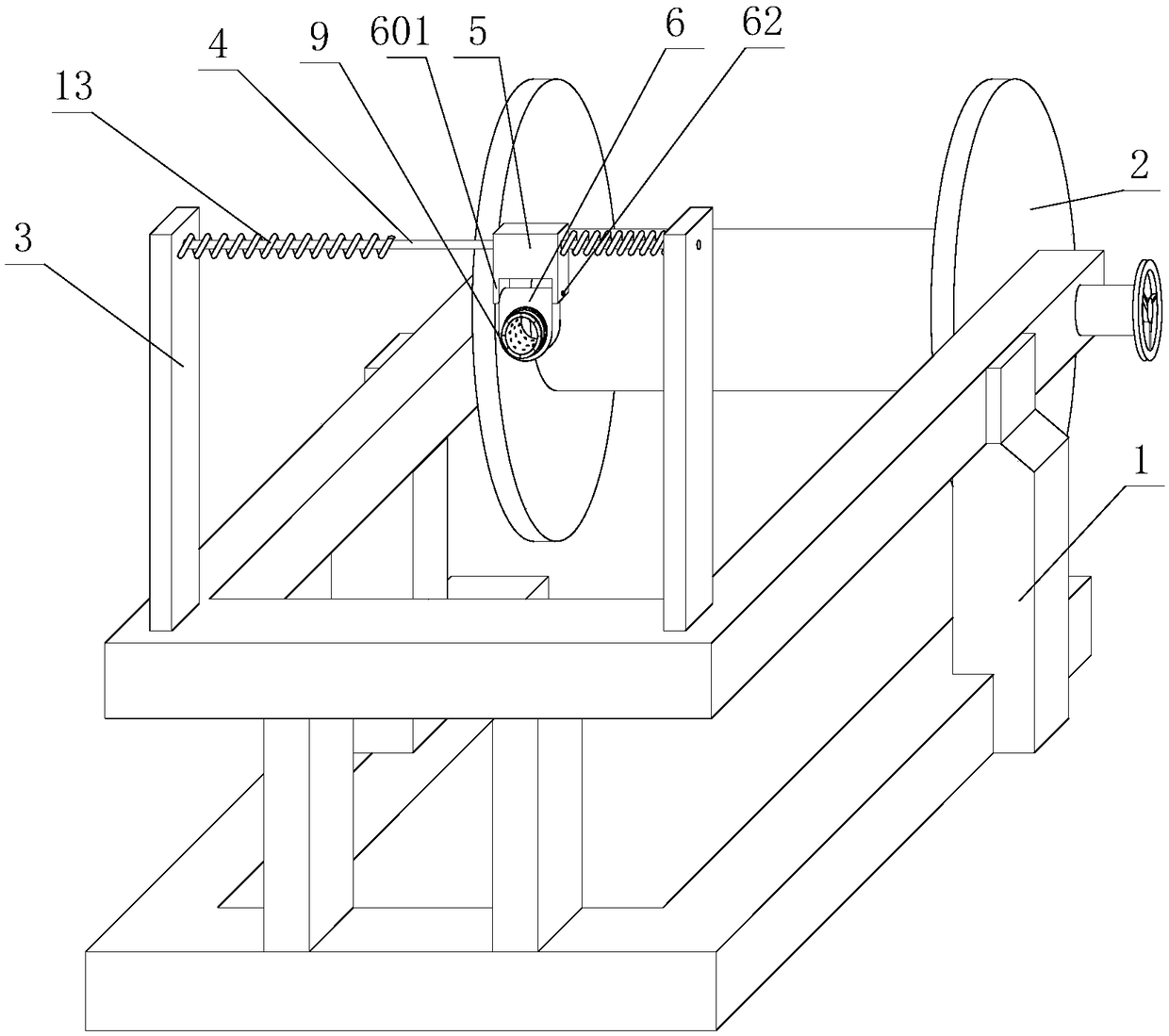

Image

  • Wire paying-off machine
  • Wire paying-off machine
  • Wire paying-off machine

Examples


Embodiment 1

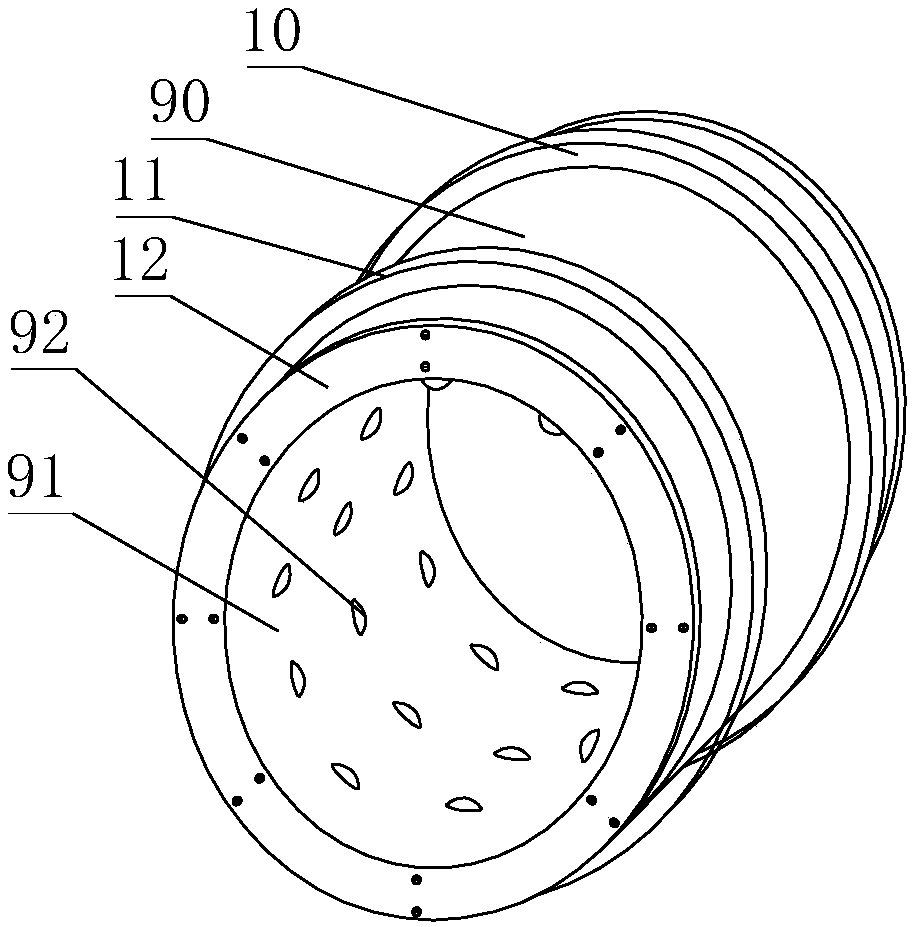
[0022] like Figure 1-3 A pay-off machine shown is a pay-off machine, including a frame 1, a winding shaft assembly 2, a support rod 3, a slide rod 4, a slide block 5, a mounting block 6 and a wire barrel 9;

[0023] The bobbin assembly 2 and the support bar 3 are arranged on the frame 1, the slide bar 4 is fixedly mounted on the support bar 3, the slide block 5 is slidably connected with the slide bar 4, the mounting block 6 is installed on the slide block 5, and the mounting block 6 There is a connecting through hole, the axis of the connecting through hole is perpendicular to the plane where the support rod 3 and the sliding rod 4 are located, and the wire barrel 9 is arranged in the through hole;

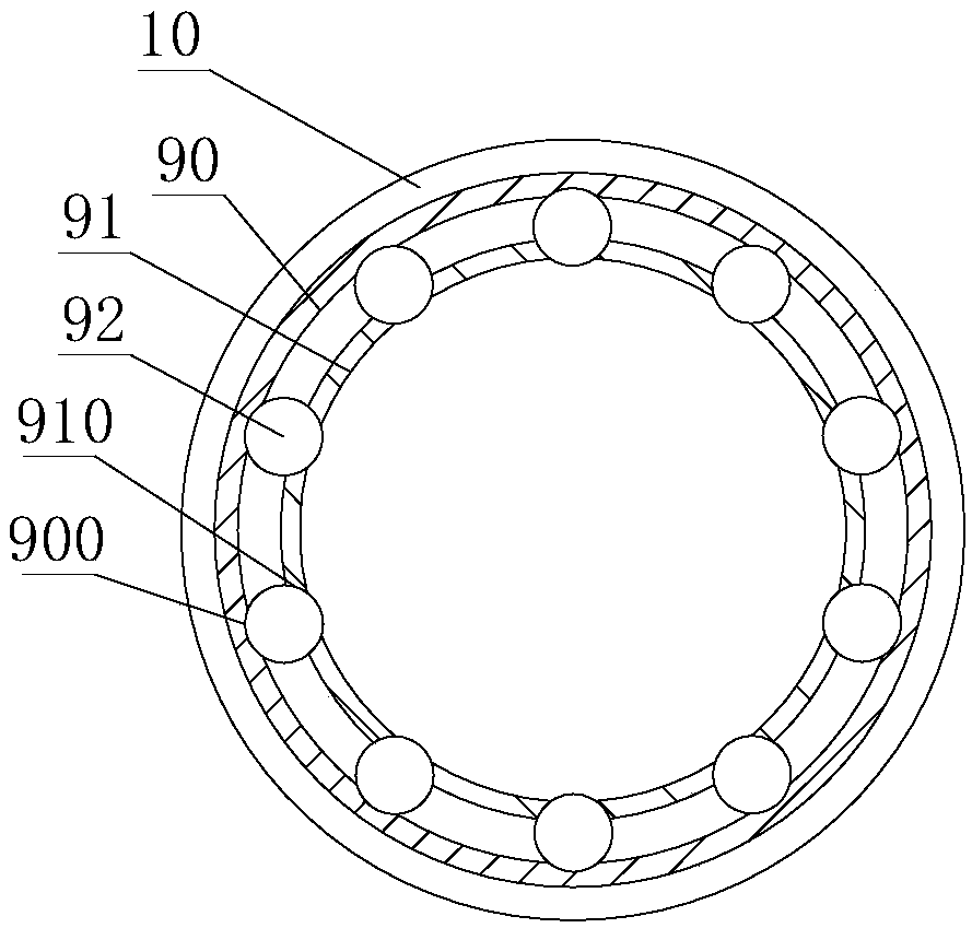
[0024] Wire passing barrel 9 comprises outer layer barrel 90, inner layer barrel 91, roller 92 and cover ring 93, inner layer barrel 90 is sleeved in outer layer barrel 90, roller 92 is arranged on outer layer barrel 90 and inner layer Between the cylinders 91, the roller 92 pr...

Embodiment 2

[0033] like Figure 4-5 As shown, the difference between the present embodiment and the first embodiment is that: preferably, an upper fixing frame 60 is provided between the slider 5 and the mounting block 6, and the upper fixing frame 60 is rotatably connected with the mounting block 6, and the slider 5 and the mounting block 6 are rotatably connected. An elastic bar 14 is arranged between the upper fixed frame 60, and the elastic bar 14 is made of rubber. Relative to the sliding block 5 swinging left and right in the vertical direction, the sliding block 5 is provided with two limit blocks 15 along the swinging direction of the elastic rod 14 . When the wire or cable is pressed against the wire barrel 9, a force is applied to the elastic rod 14 through the mounting block 6 and the upper fixing frame 60, and the elastic rod 14 is deformed to a certain extent, and the elastic rod 14 rotates relative to the slide block 5. After the rod 14 collides with the limit block 15, the...


PUM


Abstract

The invention discloses a wire paying-off machine comprising a rack, a winding shaft assembly, a supporting rod, a sliding rod, a sliding block, a mounting block and a wire passing cylinder. The winding shaft assembly and the supporting rod are arranged on the rack, the sliding rod is fixedly connected with the supporting rod, the sliding block is slidably connected with the sliding rod, the mounting block is connected with the sliding block, a connecting through hole is formed in the mounting block, the axis of the connecting through hole is perpendicular to the plane where the supporting rodand the sliding rod are located, and the wire passing cylinder is mounted in the connecting through hole in a sleeved mode; the wire passing cylinder comprises an outer layer cylinder body, an innerlayer cylinder body, a roller and a cover ring; and the inner layer cylinder body is sleeved with the outer layer cylinder body, the roller is arranged between the outer layer cylinder body and the inner layer cylinder body, the roller is protruded out of the inner wall of the inner layer cylinder body, the roller can rotate relative to the outer layer cylinder body and the inner layer cylinder body, and the cover ring is fixedly connected with the end faces of the inner layer cylinder body and the outer layer cylinder body. According to the wire paying-off machine, the pressure between a wireor a cable and the wire passing cylinder is dispersed by sliding of the sliding block on the sliding rod and rotating of the roller, thus dynamic friction between the wire or the cable and the wire passing cylinder is lowered, and then abrasion of the wire or the cable is reduced.

Description

technical field [0001] The invention relates to the technical field of wire or cable processing equipment, in particular to a wire pay-off machine. Background technique [0002] The pay-off machine is a kind of auxiliary equipment for wires and cables that is matched with the stranding machine and plays the role of pay-off. When the pay-off machine is used for wire defense, the wires or cables that are usually released first pass through the wire-passing rollers and then pass through each wire-passing guide wheel for pay-off. Since the shaft on the winding shaft assembly is relatively long, when the wire or cable on the winding shaft leaves the winding shaft, due to its position on the winding shaft, it will move left and right on the wire passing roller, and the wire or cable will generate dynamic friction during the unwinding process. The magnitude of the dynamic friction force of the wire or cable is related to the pressure of the wire or cable. The friction force genera...

Claims


Application Information

Patent Timeline
Patent Type & Authority Applications(China)
IPC IPC(8): B65H57/12B65H57/26
CPCB65H57/12B65H57/26B65H2701/34
Inventor 董红
Owner 安徽双马机械设备有限公司
Learn More