A cylinder brake transmission device

A technology of transmission and braking devices, which is applied in the direction of valve devices, engine components, machines/engines, etc., can solve the problems of knocking sound caused by movement, so as to improve the quality of the engine, prevent rapid rebound, prevent friction damage and The effect of collision

Active Publication Date: 2020-05-05
GUANGXI YUCHAI MASCH CO LTD
View PDF6 Cites 0 Cited by
  • Summary
  • Abstract
  • Description
  • Claims
  • Application Information

AI Technical Summary

Problems solved by technology

This solution is feasible, but there is also the disadvantage that the transmission chain jumps directly on the end face of the valve rod when the hydraulic cylinder is cut off, and the movement part produces a knocking sound.

Method used


Image

  • A cylinder brake transmission device
  • A cylinder brake transmission device
  • A cylinder brake transmission device

Examples


Embodiment 1

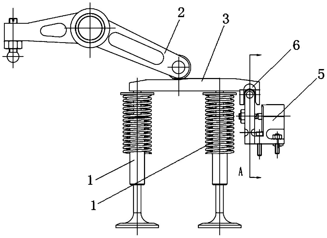
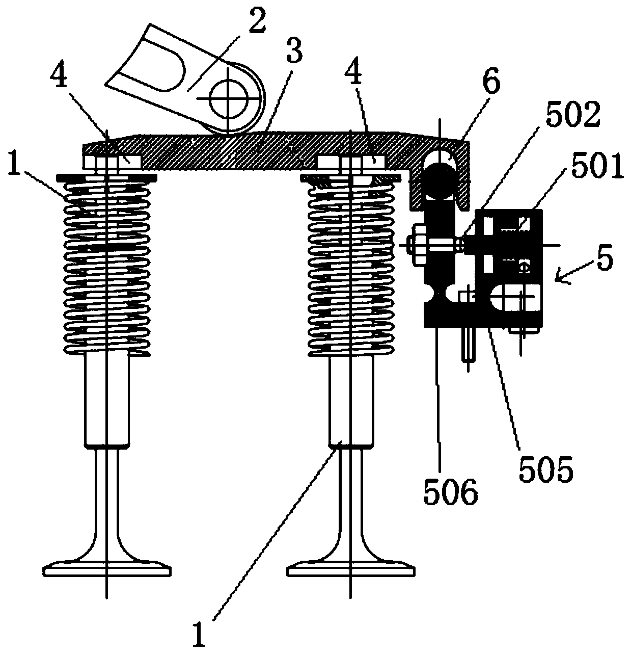
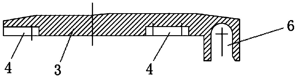
[0030] Such as Figure 1-8 As shown, an in-cylinder braking transmission device includes at least two valves 1 arranged side by side and a rocker device 2 for squeezing the valves 1, and a valve 1 and a rocker device 2 are provided between the valves 1 and the rocker device 2 to abut against them. And the valve bridge 3 that can move along the axis of the valve 1, the valve bridge 3 is provided with a guide transverse groove 4 extending perpendicular to the axis of the valve 1, and also includes a valve bridge 3 that can drive the valve bridge 3 along the direction perpendicular to the axis of the valve 1 The moving transverse braking device 5, the valve bridge 3 is provided with an axial guide groove 6 that is compatible with the transverse braking device 5; the rocker device 2 squeezes the valve bridge 3, and two or more than two The valve 1 is squeezed in the axial direction to open the valve 1, and when the valve bridge 3 is squeezed or knocked by the rocker device 2, the ...

Embodiment 2

[0043] The structure of the in-cylinder braking transmission device in this embodiment is basically the same as that of Embodiment 1, the difference is that, as attached Figure 9-10 As shown, the lateral braking device 5 in the first embodiment is adapted to one end of the valve bridge 3, and the lateral braking device 5 in the present embodiment is adapted to the middle part of the valve bridge 3; and the present embodiment Among them, the rotating shaft 507 of the lateral braking device 5 is extended outward, and the guide rollers 508 are arranged on the outside of the base 505, which facilitates the arrangement of the lateral braking device 5 and reduces the occupation of lateral space, so that the lateral braking device 5 can be arranged on Between the two valves 1, the structure is compact, and there is no need to modify the transitional structure, only the length of the rotating shaft 507 needs to be extended.


PUM


Abstract

The invention discloses a cylinder interior braking transmission device. The cylinder interior braking transmission device comprises at least two air valves arranged side by side and a rocker device for extruding the air valves. An air valve bridge which abuts against the air valves and the rocker device and can move in the axis direction of the air valves is arranged between the air valves and the rocker device. The air valve bridge is provided with a guiding transverse groove which extends in the direction perpendicular to the axis of each air valve. A transverse braking device capable of driving the air valve bridge to move in the direction perpendicular to the axis of each air valve is further included. The air valve bridge is provided with an axial guiding groove matched with the transverse braking device. The cylinder interior braking transmission device is provided with the transverse braking device to push the air valve bridge to transversely move, the buffering function is achieved, and friction sounds or noise generated when the rocker device transversely extrudes or collides with the air valve bridge is lowered; and meanwhile, engine vibration is reduced, the engine quality is improved, stable sliding is guaranteed, and the knocking sound generated by a motion pair is improved.

Description

technical field [0001] The invention relates to the technical field of engines, more specifically, it relates to an in-cylinder braking transmission device. Background technique [0002] At present, for the in-cylinder braking transmission scheme, the hydraulic cylinder is usually used to apply force along the axis of the valve stem to make the transmission chain lengthen by a certain distance at the end face of the valve stem, so that the valve (usually the exhaust valve) is not closed tightly to achieve The purpose of in-cylinder braking. This scheme is feasible, but it also has the disadvantage that the transmission chain jumps directly on the end face of the valve rod when the hydraulic cylinder is cut off, and the movement part produces a knocking sound. Contents of the invention [0003] The technical problem to be solved by the present invention is to address the above-mentioned shortcomings of the prior art, and the purpose of the present invention is to provide a...

Claims


Application Information

Patent Timeline
Patent Type & Authority Patents(China)
IPC IPC(8): F01L13/06
CPCF01L13/06
Inventor 梁振杰
Owner GUANGXI YUCHAI MASCH CO LTD
Why Eureka
Try Eureka