Rolling bearing having superthin wall

A rolling bearing, ultra-thin-wall technology, applied to bearing components, shafts and bearings, mechanical equipment, etc., to reduce friction sound or other abnormal sounds

Inactive Publication Date: 2009-02-18
NTN CORP
View PDF12 Cites 0 Cited by
  • Summary
  • Abstract
  • Description
  • Claims
  • Application Information

AI Technical Summary

Problems solved by technology

[0011] The purpose of the present invention is to overcome the defects of the existing ultra-thin-walled rolling bearings, and provide a new-type structure with ultra-thin-walled rolling bearings. The technical problem to be solved is to prevent or stop the use of ultra-thin Abnormal noise is generated in the case of wall rolling bearings, so it is more suitable for practical use and has industrial utilization value

Method used


Image

  • Rolling bearing having superthin wall
  • Rolling bearing having superthin wall
  • Rolling bearing having superthin wall

Examples


Embodiment Construction

[0047] The specific implementation, structure, features and functions of the ultra-thin-walled rolling bearing according to the present invention will be described in detail below with reference to the accompanying drawings and preferred embodiments.

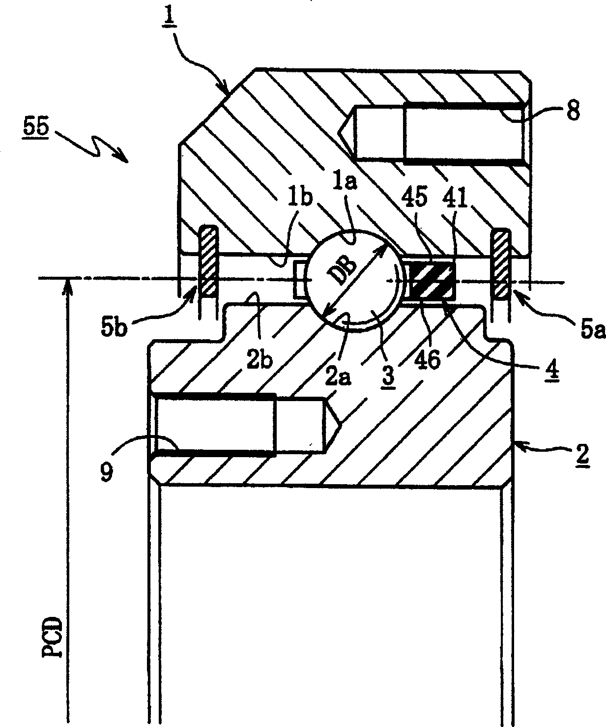
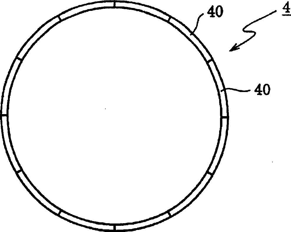
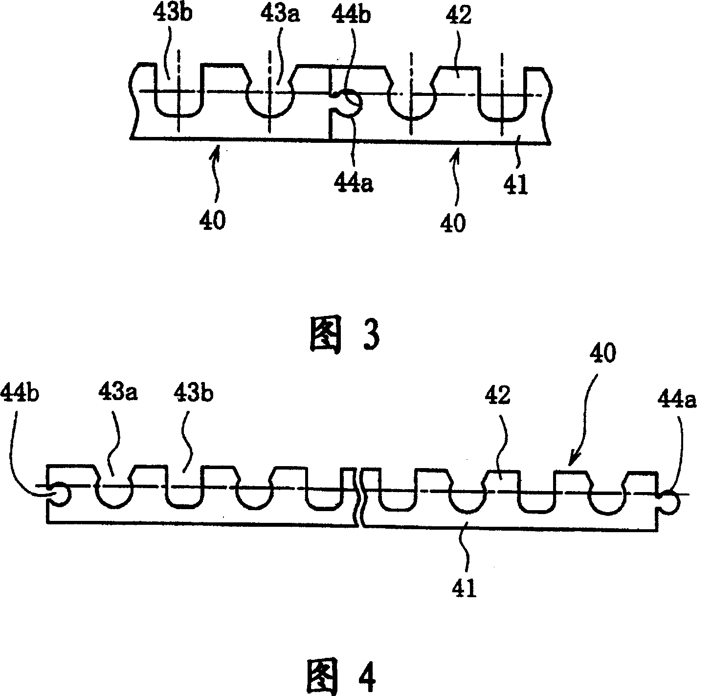
[0048] see figure 1 Shown is a schematic cross-sectional view of a rolling bearing 55 with ultra-thin walls used in CT scanning equipment. The rolling bearing 55 with ultra-thin wall of the preferred embodiment of the present invention comprises: an annular outer ring 1, an inner ring 2 concentrically arranged on the inner peripheral side of the outer ring 1, a plurality of rolling elements or balls 3 (in In this case, the balls 3 are rotatably disposed between the raceway surface 1a of the outer ring 1 and the raceway surface 2a of the inner ring 2), a cage for keeping these balls 3 positioned at equal intervals on the circumference 4 and seals 5a, 5b for sealing openings provided at opposite ends of the bearing.

[0049] In...


PUM


Abstract

The invention relates to a rolling bearing with ultrathin wall. It includes an internal ring, an external ring, several rolling components set between the tracking surfaces of internal ring and external ring and a retainer made of resin material. Said invention also provides the concrete structure and design requirement of the above-mentioned every component. Said invented rolling bearing with ultrathin wall has the function of preventing generation of abnormal sound.

Description

technical field [0001] The present invention relates to an ultra-thin-walled rolling bearing used in industrial robots, machine tools, medical equipment and similar devices, in particular to a segmented rolling bearing installed in an ultra-thin-walled rolling bearing The resin cage maintains stable performance, and its purpose is to reduce the friction noise generated when the cage and the bearing ring are in contact with each other. Background technique [0002] see Figure 8 As shown, an example of a CT scanning device, which is a medical device, is shown. In this CT scanner, X-rays generated by an X-ray tube unit 50 act on the human body through a wedge filter 51 for uniform distribution of the radiation intensity and a slit 52 for limiting the intensity distribution. X-rays passing through the human body 53 are received by a detector 54, and in the detector 54, the X-rays are converted into an electrical signal, and then the electrical signal is input into a computer n...

Claims


Application Information

Patent Timeline
Patent Type & Authority Patents(China)
IPC IPC(8): F16C33/38
Inventor 平松研吾
Owner NTN CORP
Why Eureka
Try Eureka