1000 MW thermal power unit booster pump

A technology of thermal power units and pre-pumps, which is applied to pumps, pump components, mechanical equipment, etc., can solve the problems of unfavorable long-term stable operation of power plants, high maintenance costs, and impacts, so as to ensure long-term stable operation, reduce sealing area, and ensure The effect of the sealing effect

Inactive Publication Date: 2018-12-07
POWERCHINA SPEM CO LTD
View PDF6 Cites 0 Cited by
  • Summary
  • Abstract
  • Description
  • Claims
  • Application Information

AI Technical Summary

Problems solved by technology

In this way, the entire power plant system needs to be shut down, and the maintenance cost is high. In the maintenance process, the entire pump cover needs to be disassembled. The long-term stable operation of the power plant has adverse effects

Method used


Image

  • 1000 MW thermal power unit booster pump

Examples


Embodiment 1

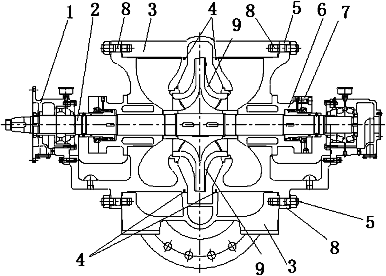
[0016] A 1000MW thermal power unit front pump, its structure is as follows figure 1 As shown, it includes a bearing chamber 1, a cooling chamber 6, a main shaft 2 and an impeller 9. The main shaft 2 runs through the bearing chamber 1 and is connected to the cooling chamber 6 through a mechanical seal 7. The impeller 9 is fixedly installed in the middle of the main shaft 2. The front pump also includes Two detachable end covers 5 and a U-shaped pump casing unit, when installed, the two end covers 5 are symmetrically installed on both sides of the bearing chamber 1, and the connecting line between the centers of the two end covers 5 is perpendicular to the main shaft 2, Both ends of the pump casing unit are fixedly connected with two end covers 5 respectively.

[0017] The bearing chamber 1 of the front pump is integrally formed, and there is no sealing problem. The end cover 5 and the pump casing unit are installed on both sides of the bearing chamber 1, that is, the radially s...


PUM


Abstract

The invention relates to a 1000 MW thermal power unit booster pump comprising a bearing chamber, a cooling chamber, a main shaft and impellers. The main shaft penetrates the bearing chamber, and is connected to the cooling chamber through a mechanical seal, and the impellers are fixedly installed at the middle part of the main shaft; the booster pump further comprises two removable end covers anda U-shaped pump shell unit; during installation, the two end covers are symmetrically installed on the both sides of the bearing chamber, and a line connecting the centers of the two end covers is perpendicular to the main shaft; and the two ends of the pump shell unit are fixedly connected to the two end covers separately. Compared with the prior art, the booster pump is of great significance inensuring the sealing effect of the sealing face, saving the pump maintenance time, improving the working efficiency of the pump maintenance, saving the operating cost of a power plant, meanwhile, prolonging the service life of the pump and ensuring the long-time stable operation of a power plant unit through design of a new booster pump subdivision sealing structure and by adopting O-rings.

Description

technical field [0001] The invention relates to the technical field of front pumps, in particular to a sealing structure for a front pump of a 1000MW thermal power unit. Background technique [0002] High-temperature and high-pressure pump sets for power plants are high-end precision rotating machinery, consisting of front pumps and main pumps. The steam turbine drives the speed-reducing gearbox to rotate, and the low-speed shaft of the gearbox drives the main shaft of the front pump to rotate. Generally speaking, the front pump is split in the middle, and the sub-pump cover and pump seat are fastened by bolts, and the split surface is sealed with green shell paper. The traditional middle-split sealing structure has a large sealing area because the contact surface is the entire middle section, so it is difficult to completely seal. As the running time increases, the green shell paper on the sealing surface will be soaked in high-temperature and high-pressure boiler water an...

Claims


Application Information

Patent Timeline
Patent Type & Authority Applications(China)
IPC IPC(8): F04D29/08F04D29/046F04D29/42
CPCF04D29/046F04D29/086F04D29/426
Inventor 陈乃娟代珣蔡国建梁杰敬敏
Owner POWERCHINA SPEM CO LTD
Why Eureka
Try Eureka