Clutch disc and clutch

A technology for clutches and moving discs, which is applied in the field of clutches, and can solve problems such as the vibration damping spring 4 not exerting the anti-torsion and vibration damping function, resonance of the clutch driven disc, noise pollution, etc.

Active Publication Date: 2021-11-16
SCHAEFFLER TECH AG & CO KG
View PDF10 Cites 0 Cited by
  • Summary
  • Abstract
  • Description
  • Claims
  • Application Information

AI Technical Summary

Problems solved by technology

[0004] The applicant found that the existing driven disc body would run idly, and the vibration damping spring 4 could not exert the function of anti-torsion and vibration reduction, and the clutch driven disc might resonate due to idle travel, resulting in noise pollution

Method used


Image

  • Clutch disc and clutch
  • Clutch disc and clutch
  • Clutch disc and clutch

Examples


Embodiment Construction

[0028] In order to make the above objects, features and advantages of the present invention more comprehensible, specific embodiments of the present invention will be described in detail below in conjunction with the accompanying drawings.

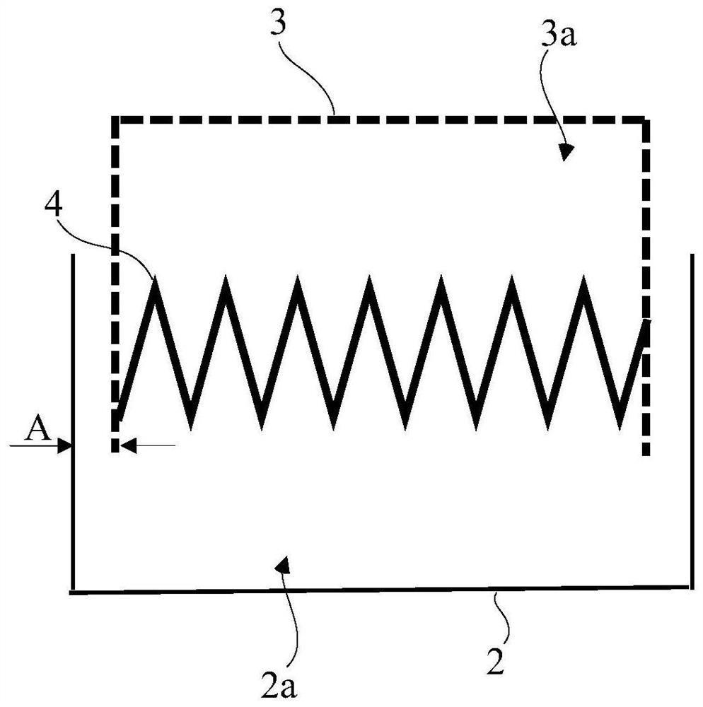
[0029] refer to figure 2 , In the prior art, the driven disc body 3 has a first hole 3a, the hub flange 2 has a second hole 2a, and the first hole 3a and the second hole 2a are axially opposite. Due to machining errors, there is a gap A ( figure 2 shown in ). The damping spring 4 is engaged with the first hole 3 a on the driven disk body 3 along its own elastic deformation direction, and is arranged with a gap between both side walls of the second hole 2 b on the hub flange 2 .

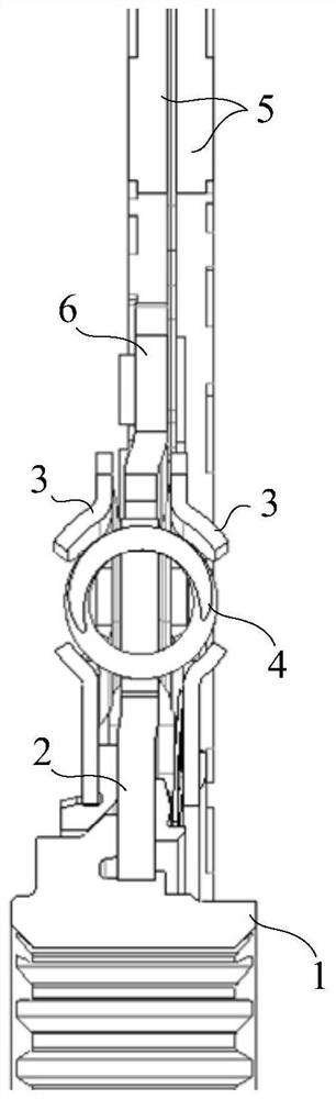
[0030] combine figure 1 As shown, under this structure, the friction plate 5 transmits the torque output by the engine to the driven disc body 3, and the driven disc body 3 will rotate relative to the hub flange 2, because the damping spring 4 and the hub fla...


PUM


Abstract

A clutch driven disc and a clutch, wherein the clutch driven disc includes: a hub arranged coaxially, a driven disc body, the hub includes a hub core, and a hub flange coaxially arranged outside the hub core ; The driven disc body has several first holes distributed circumferentially, the hub flange has several second holes distributed circumferentially, the first holes are axially opposite to the second holes; vibration damping The spring is arranged in the first hole and the second hole and has a pre-tightening force; along the elastic deformation direction, the first end of the first type damping spring is against the side wall of the first hole, and the second end is in contact with the side wall of the first hole. The side wall of the second hole is against, the first end of the second type of damping spring is against the side wall of the second hole, and the second end is against the side wall of the first hole; along the circumferential direction, the driven disc body The force received by the first type of damping spring is equal in size and opposite in direction to the force received by the second type of damping spring. The clutch driven disc of the present invention has no idle stroke, and can eliminate the resonance phenomenon caused by the idle stroke.

Description

technical field [0001] The invention relates to the technical field of clutches, in particular to a clutch driven disc and a clutch. Background technique [0002] The clutch includes a driven plate and a pressure plate, the pressure plate is connected to the flywheel on the engine, and the driven plate is connected to the input shaft of the gearbox. When the driven plate and the pressure plate are engaged, the pressure plate transmits the engine torque to the driven plate, and then the driven plate transmits torque to the gearbox; when the driven plate and the pressure plate are separated, the torque transmission between the engine and the gearbox is cut off. [0003] refer to figure 1 , the existing clutch driven disc includes: a coaxially arranged driven disc body 3 and a driven disc hub. The driven disc body 3 is connected with the friction plate 5 through the fixed plate 6, and the friction plate 5 is used to contact with the pressure plate arranged on the flywheel of ...

Claims


Application Information

Patent Timeline
Patent Type & Authority Patents(China)
IPC IPC(8): F16D13/64F16F15/123
CPCF16D13/646F16D2300/22F16F15/1232F16F15/12353
Inventor 包顺程陈广露周文敏
Owner SCHAEFFLER TECH AG & CO KG
Why Eureka
Try Eureka