Torsional vibration damper

A technology of torsional vibration and shock absorber, applied in the direction of spring/shock absorber, vibration suppression adjustment, mechanical equipment, etc., can solve expensive problems and achieve the effect of reducing costs

Pending Publication Date: 2018-12-07
SCHAEFFLER TECH AG & CO KG
View PDF8 Cites 0 Cited by
  • Summary
  • Abstract
  • Description
  • Claims
  • Application Information

AI Technical Summary

Problems solved by technology

However, this turning operation is an expensive manufacturing step, which is associated with costs

Method used


Image

  • Torsional vibration damper

Examples


Embodiment Construction

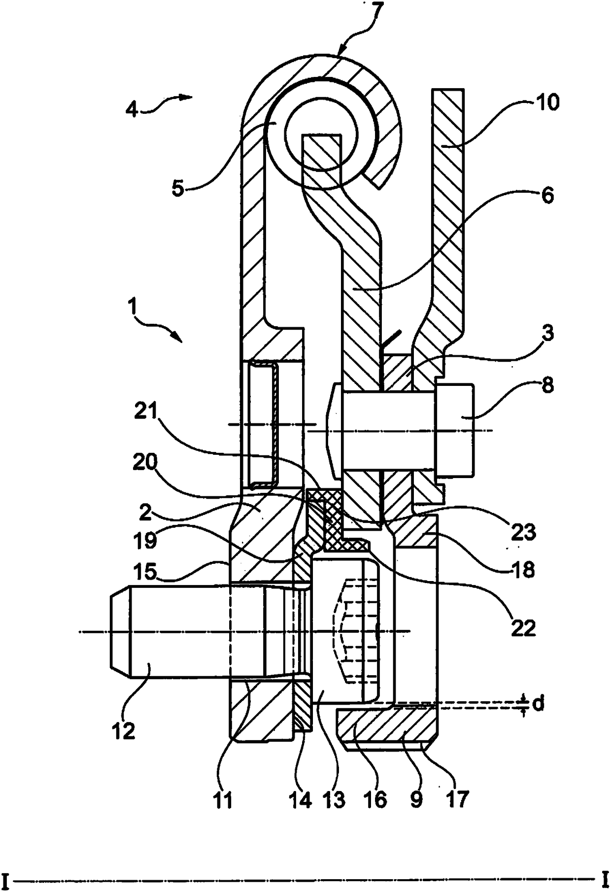
[0019] figure 1 The torsional vibration damper 1 is shown in a schematic partial section. In this case, the torsional vibration damper 1 is designed to be torsion about an axis I-I, which also constitutes a reference for the axial direction, the radial direction or the circumferential direction.

[0020] The torsional vibration damper 1 has an input element 2 and an output element 3 which are arranged torsionally relative to one another about an axis I-I. Typically, the input element 2 can be connected to an element in the drive train of the motor vehicle. The connection can be realized, for example, with the crankshaft of the internal combustion engine or also otherwise. Typically, the output element 3 can be connected to downstream elements in the drive train of the motor vehicle. The connection can be, for example, to a transmission input shaft. When using the torsional vibration damper 1 as a dual clutch damper, the torsional vibration damper 1 can be integrated into t...


PUM


Abstract

A torsional vibration damper (1) having an input element (1) and an output element (3). A damping device (4) is arranged in a torque flow between the input element (1) and the output element (3), so that the input element (1) can be twisted with respect to the output element (3) against the returning force of the damping device (4); an input element (1) is provided with a through opening (11), a bolt (12) having a bolt head (13) penetrates through the through opening, the bolt head (13) is arranged on and protrudes from a side (14) of the input element (1) facing the output element (3), the output element (3) has a flange (16) facing the input element (1) in the axial direction, the flange (16) protrudes in the axial direction towards the input element (1) so that it at least partially overlaps the bolt head (13) of the bolt (12) in the axial direction, and the flange (16) is arranged radially inwardly or radially outwardly with respect to the bolt head (13).

Description

technical field [0001] The invention relates to a torsional vibration damper, in particular for a drive train of a motor vehicle. Background technique [0002] Various torsional vibration dampers in drive trains are known. For example, clutch dampers or double clutch dampers are known which have an input element and an output element between which a damper arrangement is arranged, The output element is thus arranged torsionally against the restoring force of the damper arrangement relative to the input element at a limited angle of rotation. Depending on the configuration of the damper arrangement, torsional vibrations can thus be damped or damped. In particular in torsional vibration dampers in which the input element is not supported by means of bearings relative to the output element, during transport of the torsional vibration damper a radial displacement of the input element relative to the output element can occur, which assembly may cause problems while debugging. ...

Claims


Application Information

Patent Timeline
Patent Type & Authority Applications(China)
IPC IPC(8): F16F15/129F16F15/121
CPCF16F15/121F16F15/129F16F15/13164F16F15/13185
Inventor E·菲舍尔P·施韦德尔勒
Owner SCHAEFFLER TECH AG & CO KG
Why Eureka
Try Eureka