Cooling anti-explosion watertight valve for gas pipeline

A gas pipeline, watertight technology, applied in valve details, valve device, valve shell structure, etc., to achieve the effect of improving safety

Inactive Publication Date: 2018-12-07
淮北杰森环保科技有限公司
View PDF6 Cites 0 Cited by
  • Summary
  • Abstract
  • Description
  • Claims
  • Application Information

AI Technical Summary

Problems solved by technology

In order to solve this problem, some technical solutions are also given in the prior art. However, the structure can be simple, the temperature can be lowered bef

Method used


Image

  • Cooling anti-explosion watertight valve for gas pipeline

Examples


Embodiment 1

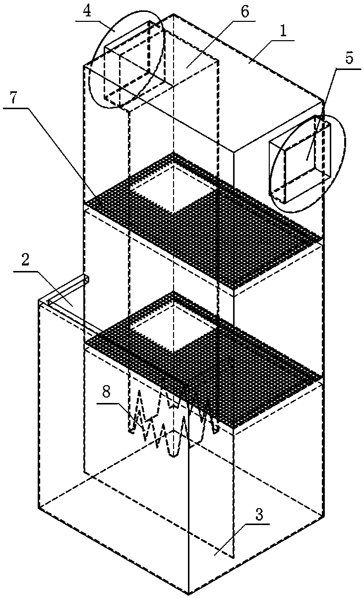
[0019] A cooling and explosion-proof watertight valve for gas pipelines, comprising a valve body, on which a cooling flame-retardant chamber 1 and a pressure relief chamber 2 are arranged, the cooling flame-retardant chamber 1 and the pressure relief chamber 2 are arranged side by side, and the two chambers There is a bottom gap 3 on the bottom of the chamber between the partitions, and the two chambers are filled with liquid and communicated through the bottom gap 3; a valve inlet 4 and a valve outlet 5 are set on the cooling flame-retardant chamber 1, and the valve inlet 4. An inner air intake pipe 6 is arranged in the cooling flame retardant chamber 1, the air outlet of the inner air inlet pipe 6 is located in the liquid-filled chamber, and the top of the pressure relief chamber 2 is open.

Embodiment 2

[0021] As a preference of Embodiment 1, the height of the pressure relief chamber 2 is lower than that of the temperature-reducing flame-retardant chamber 1 . When the pressure relief chamber is equal to or higher than the cooling flame retardant chamber, it will cause the filling liquid to enter the intake port during the pressure relief process, which is generally not acceptable.

[0022] As a further optimization of the structure, the height of the pressure relief chamber 2 is 1 / 2-1 / 3 of the height of the temperature-reducing flame-retardant chamber 1 .

[0023] As a preference, the inventors found that when the height of the pressure relief chamber 2 is 1 / 2 of the height of the temperature-reducing flame-retardant chamber 1 and the width is 1 / 2 of the width of the temperature-reducing flame-retardant chamber 1, the pressure relief speed is fast , and it will not cause the filling liquid to enter the intake end during the pressure relief process, and when the filling liquid...

Embodiment 3

[0025] As a specific structure of Embodiment 1, a valve air inlet 4 is provided on one side of the upper part of the temperature-reducing flame-retardant chamber 1 , and a valve air outlet 5 is provided on the upper part of the other side corresponding to the valve air inlet 4 .

[0026] The height of the bottom gap 3 is 1 / 35-1 / 45 of the height of the cooling flame-retardant chamber 1 .

[0027] The height of the air outlet of the inner air intake pipe 6 from the bottom of the chamber is 3 to 4 times the height of the bottom gap 3 .

[0028] The pipe body of the inner air intake pipe 6 runs through two steel mesh layers 7 , and several teeth 8 are arranged on the air outlet pipe body of the inner air intake pipe 6 .

[0029] In order to further ensure that the valve body will not leak the intake air during intake air, and will not cause the intake air to stay as air bubbles in the liquid filling, and can realize rapid pressure release when the pressure is released, the above s...


PUM


Abstract

The invention discloses a cooling anti-explosion watertight valve for a gas pipeline. The cooling anti-explosion watertight valve comprises a valve body provided with a cooling flame retardant chamberand a decompression chamber. The cooling flame retardant chamber and the decompression chamber are connected side by side. A partition between the cooling flame retardant chamber and the decompression chamber reserves bottom gaps at the bottoms of the cooling flame retardant chamber and the decompression chamber. The cooling flame retardant chamber and the decompression chamber are filled with liquid and communicate with each other through the bottom gaps. The cooling flame retardant chamber is provided with a valve gas inlet and a valve gas outlet. An inner gas inlet pipe is arranged from the valve gas inlet to the inside of the cooling flame retardant chamber. A gas outlet of the inner gas inlet pipe is located in the filling liquid. The top of the decompression chamber is open. The valve body is provided with the cooling flame retardant chamber and the decompression chamber, gas is guided into the filling liquid to achieve cooling through the inner gas inlet pipe arranged in the cooling flame retardant chamber, bubbles are prevented by teeth, a steel wire mesh layer and a polygonal ball form a filtration demisting structure, burning occurs after passing of the cooling flame retardant chamber, if backfire occurs, the cooling flame retardant chamber conducts the cooling flame retardance, the decompression chamber conducts decompression, and safety of the gas pipeline is improved greatly.

Description

technical field [0001] The invention relates to a valve, in particular to a cooling and explosion-proof watertight valve for gas pipelines. Background technique [0002] In the gas pipeline, under some conditions, due to the presence of combustible gas and oxygen in the gas pipeline, when it is introduced into the combustion furnace, there is a risk of reverse combustion when encountering an open flame. In order to solve this problem, some technical solutions are also given in the prior art. However, the structure can be simple, the temperature can be lowered before the gas is introduced into the combustion furnace, and the backflow of the gas can be prevented when the reverse combustion occurs. equipment, rarely reported. Contents of the invention [0003] The purpose of the present invention is to overcome the defects of the prior art, and provide a cooling explosion-proof watertight valve for gas pipelines, which has the functions of cooling, flame retardancy and press...

Claims


Application Information

Patent Timeline
IPC IPC(8): F16K27/00F23G7/06
CPCF16K27/00F23G7/06F23G2208/10
Inventor 李磊李停王诚
Owner 淮北杰森环保科技有限公司
Why Eureka
Try Eureka