Mounting device and method for microseismic monitoring detector

A technology for installing devices and geophones, which is applied in the direction of seismic signal receivers, etc., can solve problems such as large errors in detection results, slow pouring of concrete, and geophone jamming, etc., to improve accuracy, improve signal-to-noise ratio, and ice cubes The effect of increased intensity

Active Publication Date: 2018-12-07
SHENGLI OILFIELD XINSHENG PETROLEUM GEOPHYSICAL TECH SERVICE CO LTD
View PDF7 Cites 1 Cited by
  • Summary
  • Abstract
  • Description
  • Claims
  • Application Information

AI Technical Summary

Problems solved by technology

In the prior art, the geophone is generally hoisted to the bottom of the borehole by ropes, but since there will be loose soil, sand and gravel on the inner wall of the borehole, the geophone will touch the soil or sand during the descent of the geophone, causing the The position of the geophone is shifted, resulting in inaccurate installation position of the geophone and large errors in the detection results
In addition, if there is a lot of loose soil, sand, etc. on the inner wall of the borehole, these soils, sand, etc. are likely to block the geophone, resulting in the failure of the geophone to be installed to the bottom of the borehole.
In addition, after the geophone is installed at the bottom of the borehole, when the concrete is poured into the borehole quickly, the geophone is easy to float, tilt or even fall. In order to avoid this situation, it is usually necessary to pour the concrete very slowly, so Construction efficiency is affected

Method used


Image

  • Mounting device and method for microseismic monitoring detector
  • Mounting device and method for microseismic monitoring detector
  • Mounting device and method for microseismic monitoring detector

Examples


Embodiment Construction

[0037] In order to enable those skilled in the art to better understand the present invention, the technical solution of the present invention will be further described below in conjunction with the accompanying drawings and embodiments.

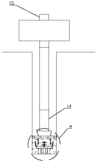
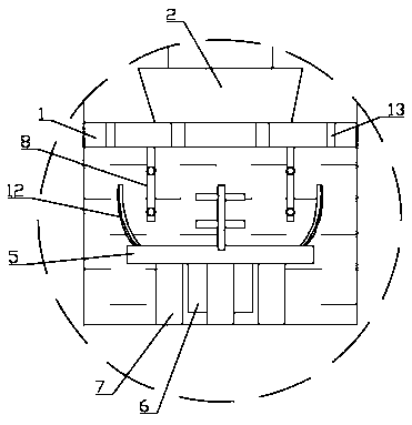
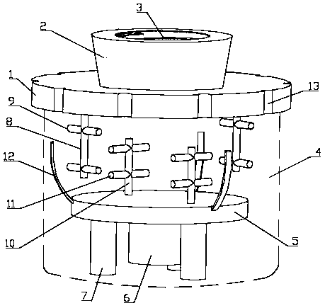
[0038] Such as Figure 1 to Figure 3 As shown, a kind of installation device of the geophone used for monitoring microseismic of the present invention comprises a push plate 1, and the middle part of the push plate 1 is provided with a through hole, and the through hole is used to pass through the signal line of the geophone 6, and the push plate 1 The top is connected with a connector 2, and the inner wall of the connector 2 is provided with an internal thread 3. When installing, the connector 2 is used as a female head, and the lower end of the drill collar 14 is used as a male head. The connector 2 is threaded with the lower end of the drill collar 14 through the internal thread 3. connect.

[0039] During installation, after the drill h...


PUM


Abstract

The invention discloses a mounting device and method for a microseismic monitoring detector and belongs to the field of the geological disaster monitoring and prevention technology. The mounting device comprises a push disk, wherein the middle of the push disk is provided with a through hole, a top portion of the push disk is connected with a connector, an inner wall of the connector is provided with inner thread, during mounting, the connector is connected with outer thread of a lower end of a drill collar through the inner thread, a bottom portion of the push disk is connected with an ice block, the ice block is the cylindrical structure, an outer diameter of the ice block is smaller than an outer diameter of the push disk, a concrete disk is sealed in the ice block, a bottom portion ofthe concrete disk is connected with a detector and a supporting pin, and length of the supporting pin is greater than length of the detector. The invention further comprises a mounting method of the detector. The mounting device is advantaged in that the detector can be smoothly mounted to the bottom of a hole in time before the hole collapses, that the bottom portion of the detector is coupled with the rock mass is guaranteed, the signal-to-noise ratio of the acquired data is improved, and the mounting device has a simple structure and is convenient to use.

Description

technical field [0001] The invention belongs to the technical field of geological disaster monitoring and prevention, and in particular relates to a geophone installation device and an installation method for monitoring micro-earthquakes. Background technique [0002] The monitoring of rocky slopes has always been a weak link in the process of landslide monitoring and early warning. Existing conventional monitoring methods such as surface displacement, deep displacement, pore water pressure and rainfall monitoring methods are ineffective in response to rocky slope deformation monitoring and early warning and forecasting. There are deficiencies in the process. Rock deformation, landslides, earthquakes and other activities will cause rock fractures due to changes in ground stress before they occur, which is the condition for generating micro-seismic signals. Compared with conventional monitoring, microseismic monitoring directly monitors the damage of rock mass and monitors t...

Claims


Application Information

Patent Timeline
Patent Type & Authority Applications(China)
IPC IPC(8): G01V1/20
CPCG01V1/20
Inventor 张俊贤谢庆明段江舟
Owner SHENGLI OILFIELD XINSHENG PETROLEUM GEOPHYSICAL TECH SERVICE CO LTD
Why Eureka
Try Eureka