A sleep-wake-up system and control method for an electric vehicle controller

A control method and state control technology are applied in the field of electric vehicle controller sleep wake-up control and electric vehicle controller sleep wake-up system, which can solve the problem of low sleep control success rate, affecting the static power consumption of the whole vehicle, and the static power consumption of the controller. Large and other problems, to achieve the effects of high reliability, reduced static power consumption, and strong anti-interference ability

Active Publication Date: 2021-08-31
VKAN CERTIFICATION & TESTING
View PDF7 Cites 0 Cited by
  • Summary
  • Abstract
  • Description
  • Claims
  • Application Information

AI Technical Summary

Problems solved by technology

[0015] 1) When the controller is in sleep mode, its MCU and CAN driving circuit are still powered on. Although the MCU is in low power consumption mode and the CAN driving circuit is in monitoring mode, the static power consumption of the controller is still relatively large, which affects the static performance of the vehicle. The above problems exist in both key sleep and CAN sleep;
[0016] 2) The above-mentioned level detection circuit needs to perform voltage comparison, signal latching, etc. These circuit structures are all composed of hardware, which leads to a complex circuit structure of the system, and is easy to introduce errors, resulting in a low success rate of CAN wake-up and sleep control, often It takes multiple CAN signals to achieve the effect

Method used


Image

  • A sleep-wake-up system and control method for an electric vehicle controller
  • A sleep-wake-up system and control method for an electric vehicle controller
  • A sleep-wake-up system and control method for an electric vehicle controller

Examples


Embodiment 1

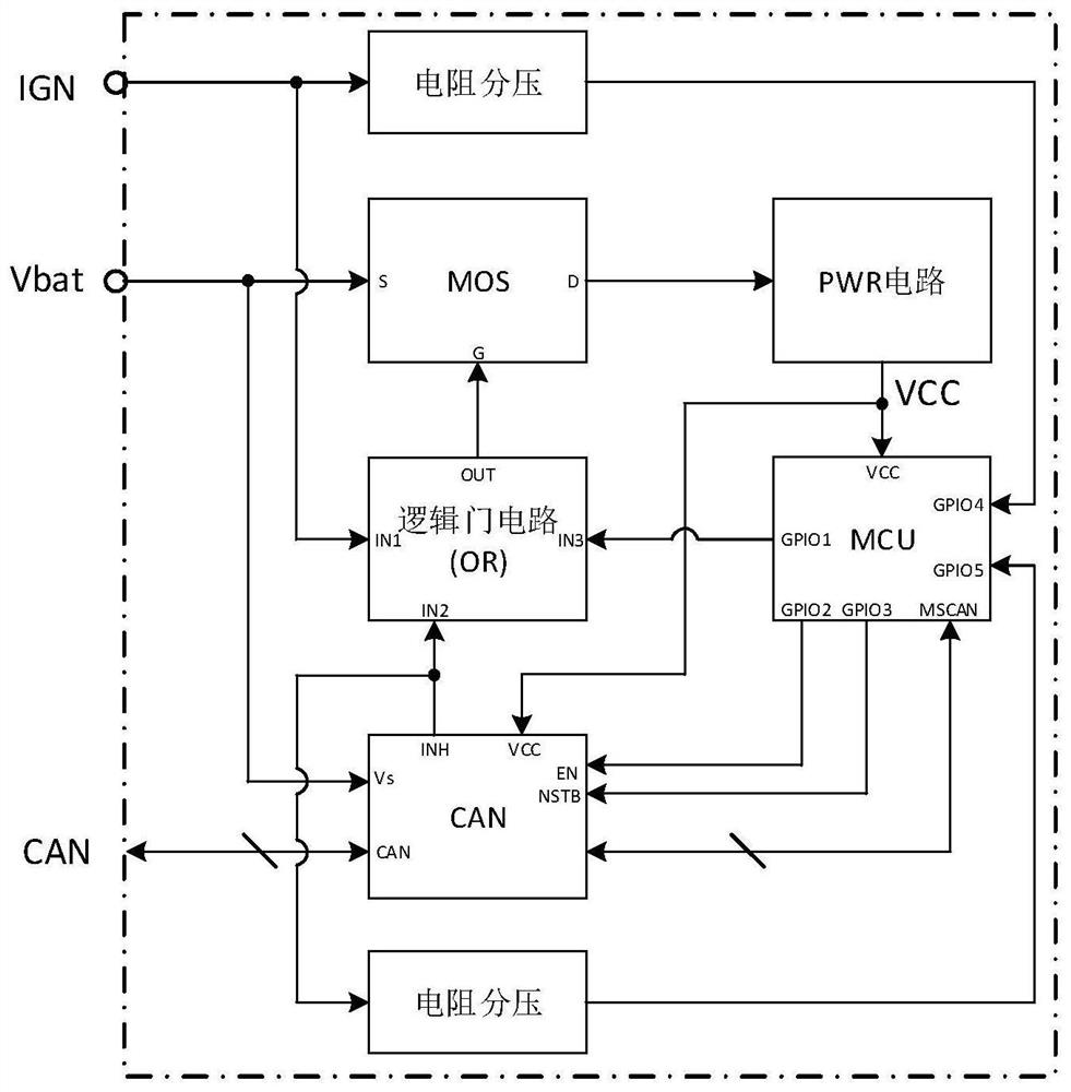
[0085] The dormancy wake-up system of Embodiment 1 is as follows: figure 2 As shown, it is a specific embodiment of the system of the third solution of the summary of the invention.

[0086] figure 2 Among the three signal terminals outside the middle dotted line, the signals output by the IGN signal terminal include IGN ON and IGN OFF, which correspond to the vehicle ignition key being in the ON and OFF positions respectively. Among them, IGN ON is a high level, and IGN OFF is a high-impedance signal. Vbat represents the battery input terminal. CAN stands for CAN bus.

[0087] figure 2 Among them, the CAN chip is a CAN chip with a wake-up function. The chip has a CAN bus signal terminal, a constant power supply input terminal Vs, a working power supply input terminal VCC, a wake-up and feedback signal output terminal INH, and a CAN signal interaction terminal (the specific pin is not marked , connected with the MSCAN end of the MCU) and state control terminals EN and ...

Embodiment 2

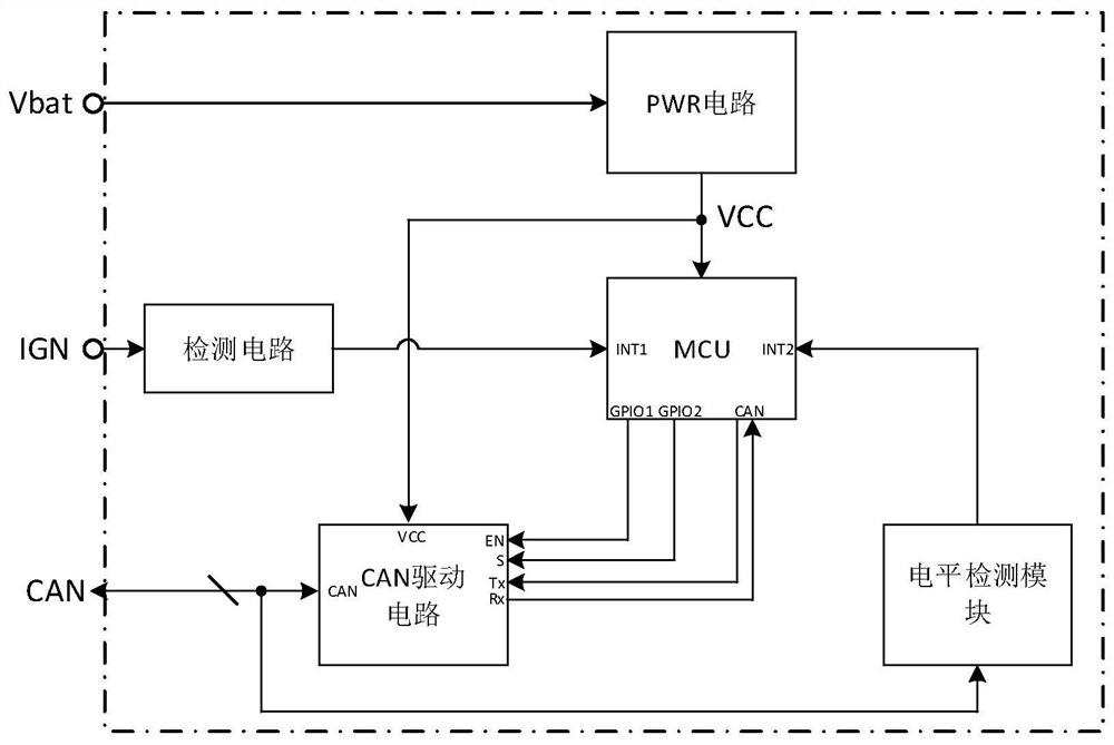
[0115] The dormancy wake-up system of embodiment two such as Figure 10 As shown, it is a specific embodiment of a system of a part of the summary of the invention. The dormancy wake-up system in the second embodiment actually only includes the parts related to CAN dormancy wake-up in the dormancy wake-up system in the first embodiment. The difference from the first embodiment is mainly reflected in the logic gate circuit and the program configuration in the MCU.

[0116] In the dormancy wake-up system of embodiment two, the input end of its logic gate circuit is connected to the wake-up and feedback signal output end of the CAN chip, and the output end is connected to the gate of the MOS tube. After the input is floating (the state feedback signal entering the dormant mode), The MOS tube is controlled to be disconnected, and the MOS tube is controlled to be switched on after the input is at a high level (both the wake-up signal and the state feedback signal for entering the ...

Embodiment 3

[0122] The dormancy wake-up system of embodiment three such as Figure 11 As shown, it is a specific embodiment of the system of the second solution of the summary of the invention. The dormancy wake-up system of the third embodiment is only based on the second embodiment, adding an input of a logic gate circuit, and the input signal is output by the MCU. The difference from the second embodiment is mainly reflected in the logic gate circuit and the program configuration in the MCU.

[0123] After the logic gate circuit of the dormancy wake-up system of the third embodiment is entered as the state feedback signal (floating) for entering the dormancy mode and the confirmation signal (low level) for controlling entering the dormancy mode, the control MOS tube block is disconnected, and the input is wake-up After the signal (high level) or the confirmation signal (high level) for controlling entering the working mode or the state feedback signal (high level) for entering the wor...


PUM


Abstract

The invention relates to a dormancy wake-up system and a control method for an electric vehicle controller. The system includes a CAN chip with a wake-up function, a logic gate circuit, a PWR module, an MCU, and a switch module. The system adds a switch module before the PWR circuit module. , through the logic gate circuit to control the closing and opening of the switch module, so as to control the working power of the CAN chip and the MCU to be disconnected when the controller is static, so that the static power consumption of the controller can be minimized, and then the CAN chip with wake-up function can be used in the When the working power supply is disconnected, it monitors whether there is a CAN message on the CAN bus and sends out a wake-up signal, and uses this signal to trigger the logic gate circuit to control the switch module to close, so that the MCU and CAN chip are powered on again, thereby supporting the controller to resume In the working mode, the system of the present invention not only has low static power consumption, but also has a simple circuit structure, and the success rate of CAN wake-up and sleep is high.

Description

technical field [0001] The invention belongs to the field of electric vehicle control, in particular to an electric vehicle controller dormancy wake-up system, and also relates to a dormancy wake-up control method for the electric vehicle controller. Background technique [0002] ECU (abbreviation of Electronic Control Unit, Chinese translation: controller) sleep is to make ECU enter sleep mode, wake up is to switch ECU from sleep mode to work mode, ECU sleep can reduce ECU static power consumption, thereby reducing vehicle static (parking) time) power consumption. An electric car has multiple controllers. When the car is parked, its ECU is generally in sleep mode. At this time, its static power consumption directly affects the output power of the battery. The greater the static power consumption of the ECU, the faster the battery power will be consumed, and the higher the battery capacity requirement is, because the battery is exhausted, which will not only cause the car t...

Claims


Application Information

Patent Timeline
Patent Type & Authority Patents(China)
IPC IPC(8): G05B19/042G06F1/3215
CPCG05B19/0428G05B2219/2603G05B2219/2637G06F1/3206
Inventor 张仕彬邓俊泳黄鲲车汉生张旺威
Owner VKAN CERTIFICATION & TESTING
Why Eureka
Try Eureka