Eureka AIR delivers breakthrough ideas for toughest innovation challenges, trusted by R&D personnel around the world.

Bandgap reference voltage source

A reference voltage source and reference circuit technology, applied in the field of electronics, can solve problems such as large temperature coefficient, and achieve the effects of low temperature coefficient, high power supply rejection ratio, and lower temperature coefficient

Active Publication Date: 2012-07-18
UNIV OF ELECTRONICS SCI & TECH OF CHINA
View PDF5 Cites 28 Cited by
  • Summary
  • Abstract
  • Description
  • Claims
  • Application Information

AI Technical Summary

Problems solved by technology

[0005] The purpose of the present invention is to solve the problem of large temperature coefficient of the existing first-order linear compensation reference voltage source, and propose a bandgap reference voltage source

Method used


Image

  • Bandgap reference voltage source
  • Bandgap reference voltage source
  • Bandgap reference voltage source

Examples


Embodiment Construction

[0018] The present invention will be further described below in conjunction with the accompanying drawings and specific embodiments.

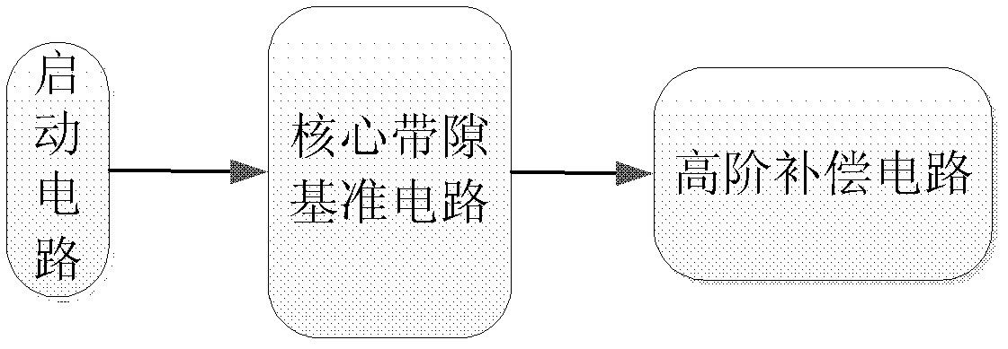
[0019] Such as figure 2 As shown, the bandgap reference voltage source of the present invention comprises a start-up circuit, a core bandgap reference circuit and a high-order compensation circuit, the core bandgap reference circuit is used to generate a reference output voltage, and the high-order compensation circuit segmentally compensated by the core bandgap The reference output voltage generated by the reference circuit.

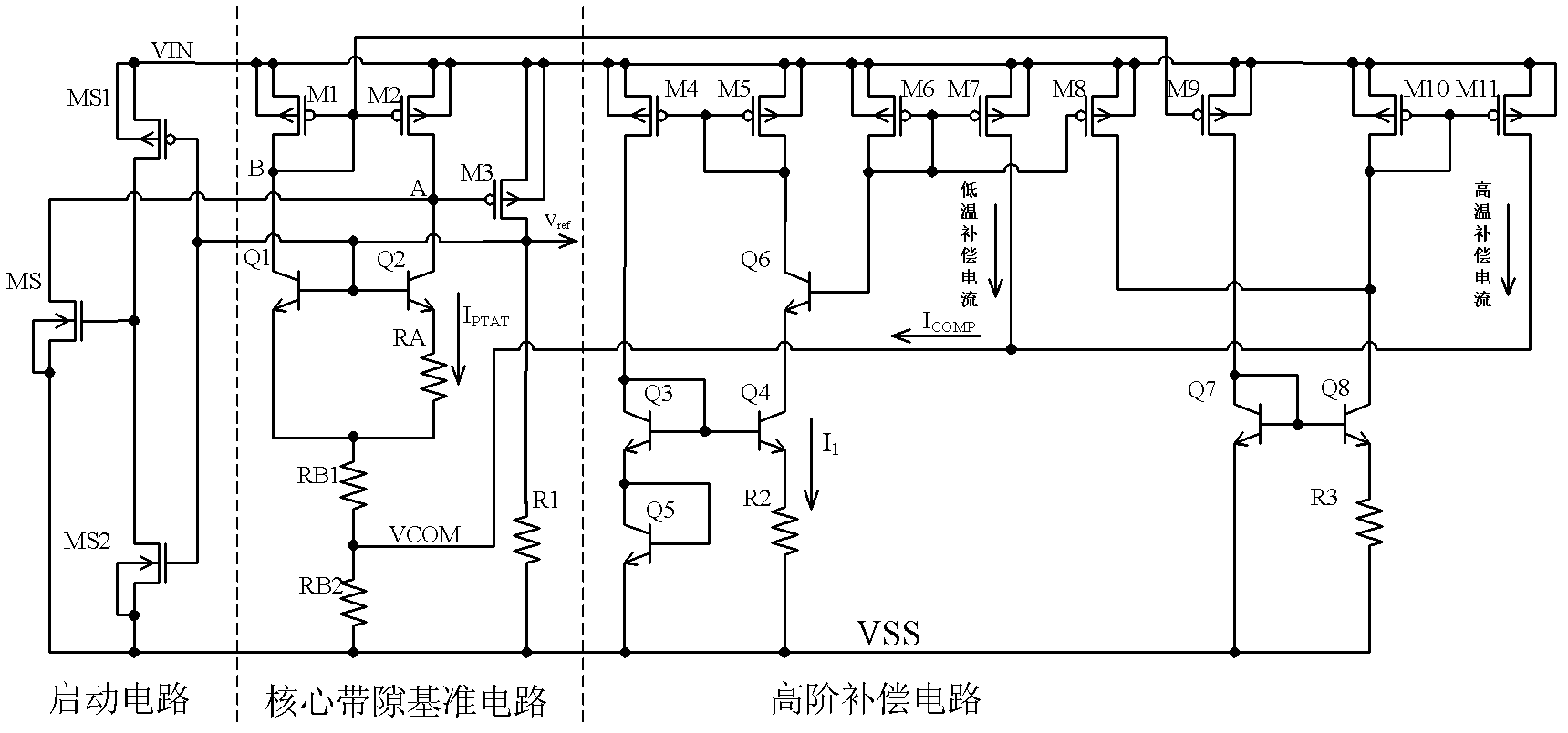
[0020] The specific circuit diagram is as image 3 As shown, among them,

[0021] The core bandgap reference circuit includes: PMOS transistors M1, M2, M3, NPN transistors Q1, Q2, and resistance units R1, RB1, RB2, RA;

[0022] The high-order compensation circuit includes: PMOS transistors M4, M5, M6, M7, M8, M9, M10, M11, NPN transistors Q3, Q4, Q5, Q6, Q7, Q8, and resistance units R2, R3;

[0023] The specific con...


PUM


Abstract

The invention discloses a bandgap reference voltage source which comprises a starting circuit, a core bandgap reference circuit and a high-order compensation circuit. The core bandgap reference circuit comprises PMOS tubes M1, M2 and M3, NPN triodes Q1 and Q2 and resistance units R1, RB1, RB2 and RA; and the high-order compensation circuit comprises PMOS tubes M4, M5, M6, M7, M8, M9, M10 and M11, NPN triodes Q3, Q4, Q5, Q6, Q7 and Q8 and resistance units R2 and R3. The bandgap reference voltage source disclosed by the invention adopts the high-order compensation circuit, thereby the temperature coefficient is reduced greatly; the circuits adopt the resistance ratio, thus the circuits can not be affected by the absolute value of the resistance, and the influence of the temperature coefficient of the resistance to the output quantity can be reduced. The bandgap reference voltage source has high power supply rejection ratio and can ensure that the circuits can resist the interference of a power supply.

Description

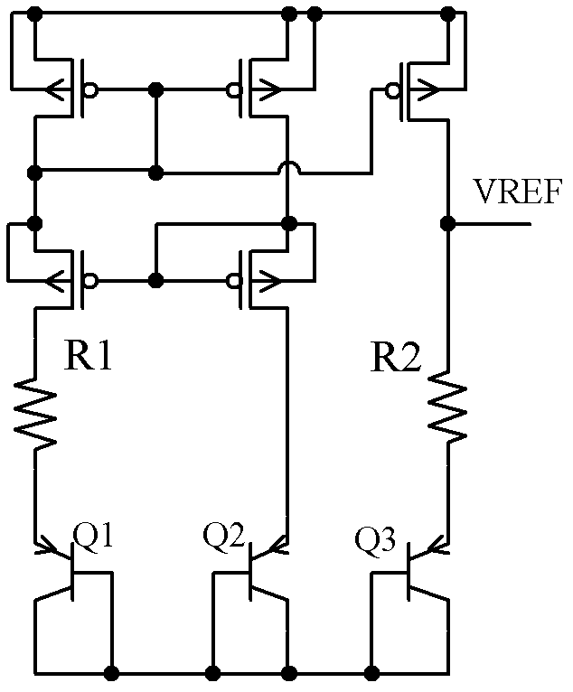
technical field [0001] The invention belongs to the technical field of electronics, and in particular relates to the design of a reference voltage source (Voltage Reference). Background technique [0002] The reference voltage source is often used as a basic circuit unit in power converters, analog and digital converters, and power amplifiers. Its purpose is to generate a constant voltage that does not vary with temperature and voltage. Its temperature coefficient (TC, Temperature Coefficient) and power supply The rejection ratio (PSRR, Power Supply Rejection Ratio) largely determines the quality of the system performance. [0003] Traditional voltage reference sources such as figure 1 Shown: A negative temperature coefficient of V EB3 voltage plus a positive temperature coefficient of ΔV BE Voltage, the two are summed to produce a voltage that is very low in temperature, and the formula for the bandgap reference voltage is: Among them, V BE is the base emitter voltage...

Claims


Application Information

Patent Timeline
Patent Type & Authority Applications(China)
IPC IPC(8): G05F1/56
Inventor 周泽坤张竹贤徐祥柱石跃黄建刚邱实明鑫张波
Owner UNIV OF ELECTRONICS SCI & TECH OF CHINA
Why Eureka
Eureka Blog
Learn More