Printing control method f

A printing control and printer technology, applied in the direction of digital output to printing units, instruments, electrical digital data processing, etc., can solve problems such as aging of mechanical parts and electronic components, affecting printing quality, paper deformation, etc.

Inactive Publication Date: 2018-12-07
阜阳市金天数码科技有限公司
View PDF5 Cites 0 Cited by
  • Summary
  • Abstract
  • Description
  • Claims
  • Application Information

AI Technical Summary

Problems solved by technology

However, when the printer is in use, a large amount of heat will accumulate with the internal operation. On the one hand, the accumulated heat will cause the paper to be deformed by heat, affect the printing quality and even cause paper jams; on the other

Method used


Image

  • Printing control method f
  • Printing control method f
  • Printing control method f

Examples


Embodiment 1

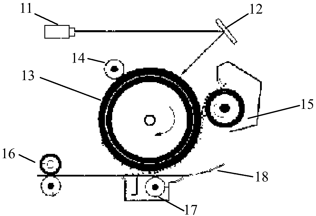
[0025] figure 1 A schematic diagram showing the working principle of a typical laser printer. Such as figure 1 As shown, the printer can include a laser 11 for emitting a laser beam; a mirror 12 for reflecting the laser beam to a photosensitive drum 13; a charging roller 14 for charging the printing roller 13; a developing roller 15; a pair of fixing rollers 16 (upper and lower rolls); and a transfer roll 17 . The printing paper 18 is conveyed to a pair of fixing rollers 16 after passing through the transfer roller 17 . The fixing roller 16 is provided with heater lamps (not shown). Apart from figure 1 In addition to the components shown in the printer, the printer may also include other known components, such as paper trays, paper feed mechanisms, and the like.

[0026] The printer may also include a control system, such as a controller, data interface, display, and the like.

[0027] Because the printer needs to heat the printing paper during the printing process, when...

Embodiment 2

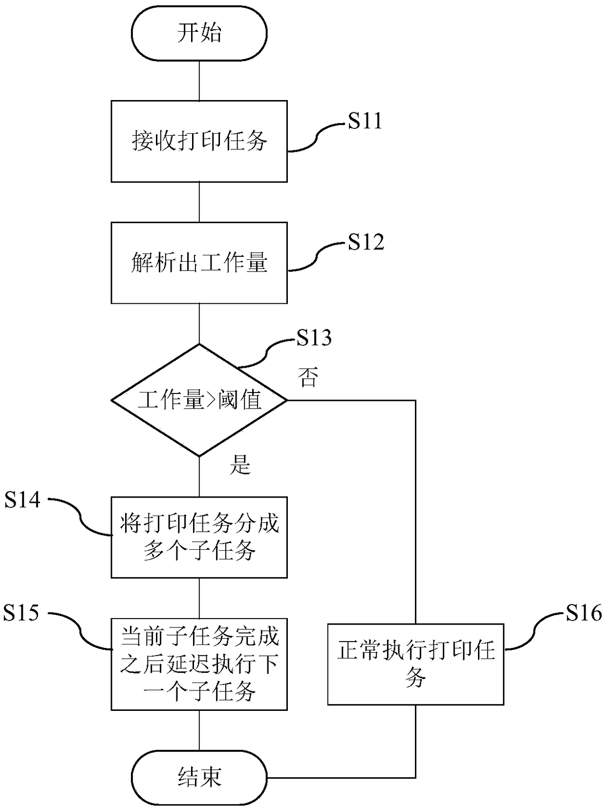
[0041] Figure 4 A flowchart of a control method according to an embodiment of the present invention is shown. Such as Figure 4 As shown, the printer variable speed temperature control method according to the embodiment of the present invention includes the following steps:

[0042] 1) Establish a temperature-printing speed data table inside the printer;

[0043] 2) Detect the temperature inside the printer in real time, and find the temperature-printing speed data table according to the temperature inside the printer to obtain the printing speed to be adjusted;

[0044] 3) Control the printing speed of the internal printing unit (or printing mechanism) of the printer according to the printing speed to be adjusted.

[0045] When searching the temperature-printing speed data table according to the temperature inside the printer in step 2) to obtain the printing speed to be adjusted, if the temperature inside the printer exceeds the preset temperature threshold, an error mes...

Embodiment 3

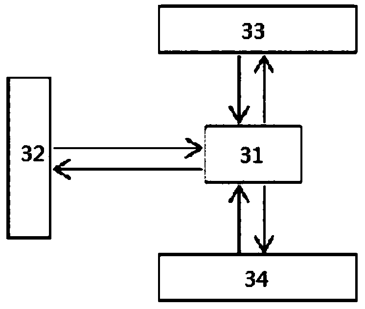
[0049] In addition to reducing the temperature through the printer control method in Embodiment 1, other methods can also be used to reduce the temperature. Figure 5 A schematic structural diagram of a printer according to an embodiment of the present invention is shown. Such as Figure 5 As mentioned, in addition to the components that can be found in a typical printer, the printer can also include ventilation located in the paper exit area of ​​the printer. The ventilation device may include at least one side air outlet 41 inside the paper output area of ​​the printer and an air supply device inside the main body of the printer. The air supply device may include, but not limited to, a fan, an air pump, and the like. In one example, the shape of the air outlet 41 may be a slot on at least one side inside the paper output area. In another example, the shape of the air outlet 41 may be a plurality of air outlets on at least one side inside the paper output area. Those skil...


PUM


Abstract

The invention discloses a printing control method. A printer comprises a ventilation device, comprising an air supply device and an air outlet arranged in a paper outlet area of the printer. The method comprises the following steps: receiving a plurality of queued printing tasks; analyzing the received current print job and the next print job to obtain the first and second workloads; judging whether the first workload is greater than a set threshold; when it is judged that the first workload is greater than a set threshold value, obtaining a mapping table between the workload and the printingspeed, dividing the current printing job into a plurality of consecutive sub-tasks, and starting the ventilation device; controlling the printing speed according to the mapping table and the first workload; after executing the current subtask, deferring execution of the next subtask; judging whether the sum of the workload of the last sub-task and the second workload is greater than the set threshold; and if it is determined that the sum is greater than the set threshold value, delaying the execution of the next print job after the execution of the last sub-job.

Description

technical field [0001] The present invention relates to the field of printers, in particular to a printing control method. Background technique [0002] Printers have become one of the commonly used equipment in office and household due to their ability to quickly print out various files, bringing great convenience to human work and life. However, when the printer is in use, a large amount of heat will accumulate with the internal operation. On the one hand, the accumulated heat will cause the paper to be deformed by heat, affect the printing quality and even cause paper jams; on the other hand, the accumulated heat will directly cause the printer to The aging of internal mechanical parts and electronic components will reduce the service life of the printer. In addition, during continuous printing, the printed paper will also have high heat. Contents of the invention [0003] The object of the present invention is to provide a printing control method in order to overcome ...

Claims


Application Information

Patent Timeline
IPC IPC(8): G06F3/12
CPCG06F3/121G06F3/1259G06F3/126G06F3/1284
Inventor 张丽影
Owner 阜阳市金天数码科技有限公司
Why Eureka
Try Eureka