Vehicle red light running detection method and system
A technology for running red lights and vehicles, which is applied in the field of detection of vehicles running red lights. It can solve problems such as death, violation of traffic laws and regulations, and losses, and achieve the effects of maintaining safety, reducing the probability of traffic accidents, and high accuracy
- Summary
- Abstract
- Description
- Claims
- Application Information
AI Technical Summary
Problems solved by technology
Method used
Image
Examples
Embodiment 1
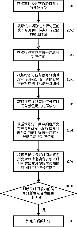
[0039] Embodiment 1, with reference to attached figure 1 , a method for detecting a vehicle running a red light, comprising the following steps:
[0040] Step S101: Obtain the driving orientation of the vehicle passing through the traffic intersection.
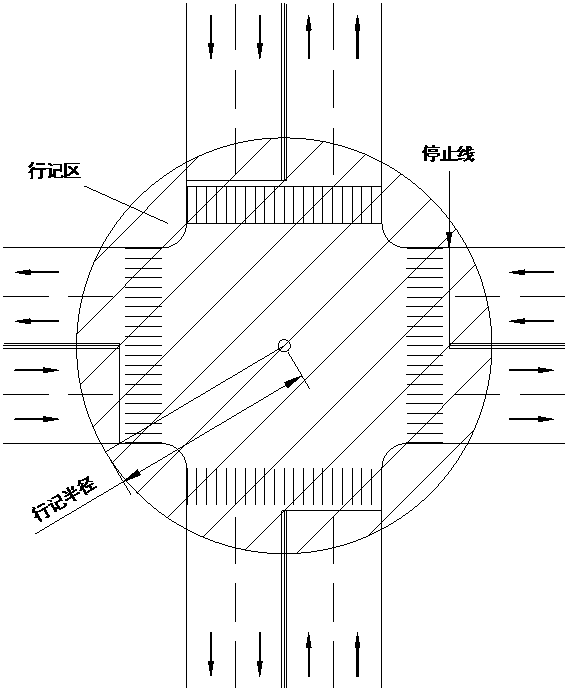
[0041] To judge whether a vehicle runs a red light, four elements are required. One is to determine the driving direction, entry position, and exit position of the vehicle at the traffic intersection. After the synthesis, it is the vehicle’s driving direction. The second is to determine the target signal light corresponding to the vehicle’s driving direction. The third is to determine the color change state of the target signal light when the vehicle is driving at the intersection, and the fourth is to determine the color state of the target signal light before the vehicle crosses the stop line at the entrance of the traffic intersection. The four are indispensable and need to be advanced layer by layer to correctly judge the ...
Embodiment 2
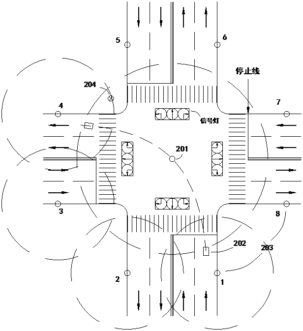
[0062] Embodiment 2: with reference to attached Figure 3-5 , this embodiment specifically introduces a system based on the method of Embodiment 1, specifically, a vehicle red light detection system, including a central signal transmitter 201 set at the very center of the traffic intersection, and an electronic tag 202 set on the vehicle , the entrance and exit signal transmitter 203 arranged at the entrance and exit of the traffic intersection, the fixed gateway 204 and the data platform 205 arranged at the roadside of the traffic intersection; the entrance and exit signal transmitter 203 includes the entrance signal transmitter and the exit signal transmitter, and the entrance signal transmitter cycle The radio frequency signal including the entrance number is sent externally, and the signal coverage includes the entrance lane area of the traffic intersection; the exit signal transmitter periodically sends the radio frequency signal including the exit number, and the signal...
Embodiment 3
[0066] Embodiment 3: with reference to attached Figure 6-8 , this embodiment specifically introduces the second system to which the method of Embodiment 1 can be applied. Specifically, a vehicle red light detection system includes a central signal transmitter 301 arranged at the very center of a traffic intersection, and a vehicle with The electronic tags 302 and data platform 303 of the positioning module and the mobile communication module; the central signal transmitter 301 periodically sends out radio frequency signals including node information, the signal coverage includes the line record area, and the node information includes the current node time, driving Azimuth and signal light number comparison information; electronic tag 302 receives and records the node information sent by central signal transmitter 301 during the process of driving in the record area; electronic tag 302 starts to locate and record position information when it first receives node information, and...
PUM
 Abstract
Description
Claims
Application Information
 - R&D
- Intellectual Property
- Life Sciences
- Materials
- Tech Scout
- Unparalleled Data Quality
- Higher Quality Content
- 60% Fewer Hallucinations
Browse by: Latest US Patents, China's latest patents, Technical Efficacy Thesaurus, Application Domain, Technology Topic, Popular Technical Reports.
© 2025 PatSnap. All rights reserved.Legal|Privacy policy|Modern Slavery Act Transparency Statement|Sitemap|About US| Contact US: help@patsnap.com


