Organic electroluminescence device and organic electroluminescence device
A technology of electroluminescent devices and electroluminescent devices, which is applied in the direction of electric solid-state devices, electrical components, semiconductor devices, etc., can solve problems such as easy to be lit at the same time, low grayscale color shift, etc., to improve display quality and reduce The effect of injecting potential barriers and solving the problem of color shift
- Summary
- Abstract
- Description
- Claims
- Application Information
AI Technical Summary
Problems solved by technology
Method used
Image
Examples
Embodiment 1
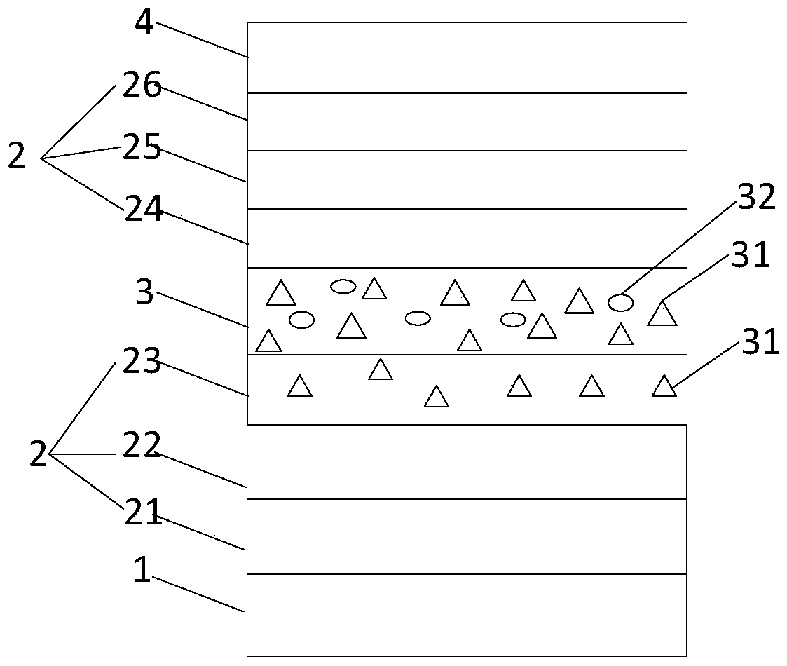
[0041] An embodiment of the present invention provides an organic electroluminescent device, such as figure 2 As shown, it includes a first electrode layer 1 , a carrier functional layer 2 , a light emitting layer 3 and a second electrode layer 4 which are stacked. The first electrode layer 1 is an anode, and the second electrode layer 4 is a cathode; or the first electrode layer 1 is a cathode, and the second electrode layer 4 is an anode. In the following, the first electrode layer 1 is used as an anode, and the second electrode layer 4 is used as a cathode as an example for illustration. The carrier functional layer 2 has one or more layers and is disposed between the light emitting layer 3 and the first electrode layer 1 and / or between the light emitting layer 3 and the second electrode layer 4 .
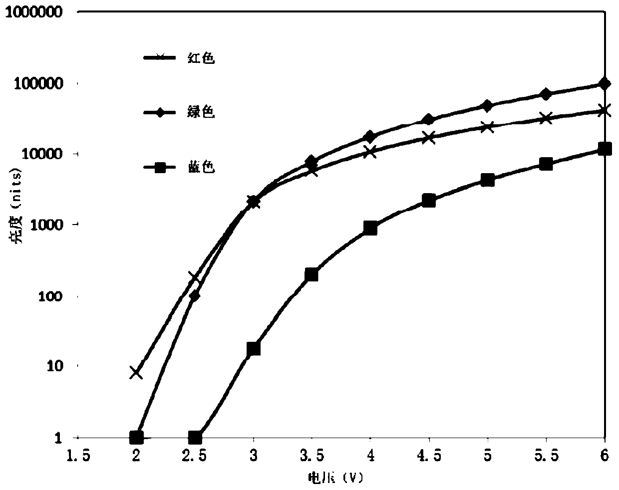
[0042] In the prior art, the process of lighting an organic electroluminescent device is to apply a certain driving voltage to the first electrode layer 1 and the second elect...
Embodiment 2
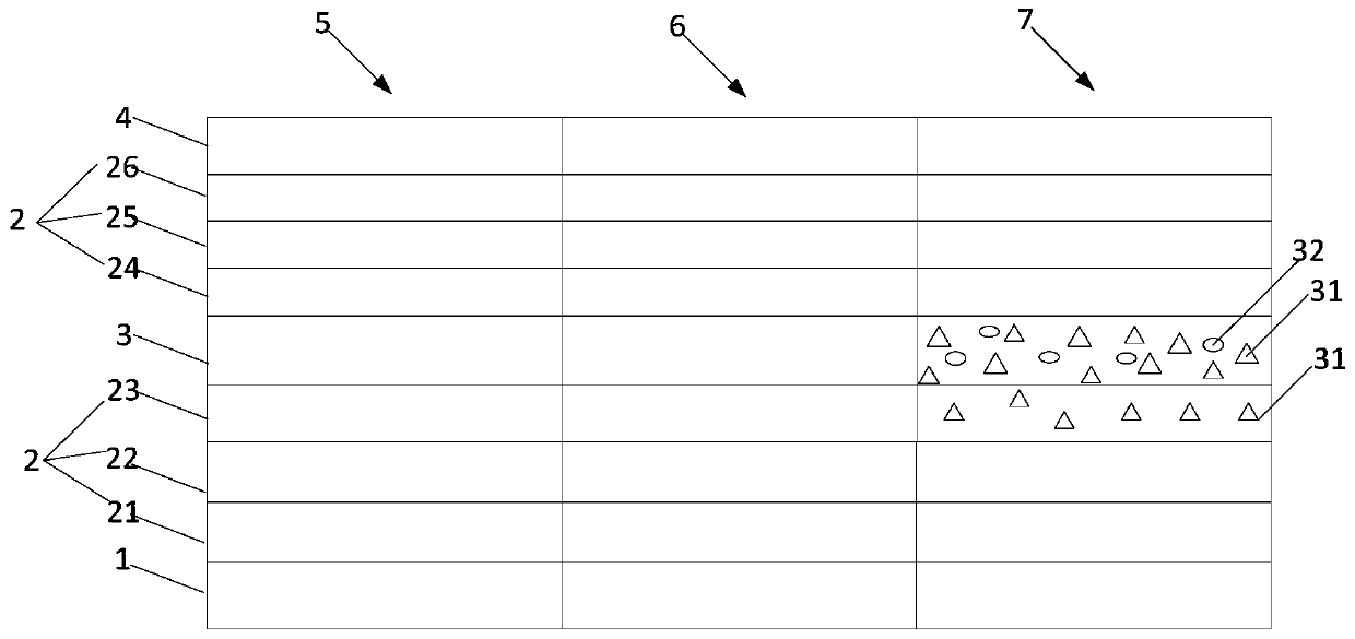
[0060] An embodiment of the present invention provides an organic electroluminescent device, including several pixel units distributed in an array, such as image 3 As shown, each pixel unit includes a red light sub-pixel unit 5 , a green light sub-pixel unit 6 and a blue light sub-pixel unit 7 .
[0061] Each sub-pixel unit includes a stacked first electrode layer 1, a carrier functional layer 2, a light-emitting layer 3, and a second electrode layer 4, a red sub-pixel unit 5, a green sub-pixel unit 6, and a blue sub-pixel unit 7 The light emitting layers 3 in the figure are red light emitting layer, green light emitting layer and blue light emitting layer respectively.
[0062] At least one carrier functional layer 2 close to the blue light emitting layer in the blue light sub-pixel unit 7 is doped with materials in the blue light emitting layer.
[0063] For specific content, reference may be made to the description in Embodiment 1, and details are not repeated here.
[0...
Embodiment 3
[0070] The embodiment of the present invention provides a specific organic electroluminescence device, including several pixel units distributed in an array, and each pixel unit includes a red sub-pixel unit 5 , a green sub-pixel unit 6 and a blue sub-pixel unit 7 .
[0071] Each sub-pixel unit includes a first electrode layer 1 (anode), a carrier functional layer 2 (hole injection layer 21, a hole transport layer 22, an electron blocking layer 23), a light-emitting layer 3, a carrier Flow sub-pixel unit 5, green sub-pixel unit 6 and blue sub-pixel unit 7 The light-emitting layers 3 are respectively a red light-emitting layer, a green light-emitting layer and a blue light-emitting layer.
[0072] Wherein, the blue light-emitting layer 3 includes a host material CBP and a guest material BCzVBI, and the electron blocking layer 23 in the blue sub-pixel unit 7 is doped with the host material CBP in the blue light-emitting layer, and the doping ratio is 25 wt%. The electron blocki...
PUM
| Property | Measurement | Unit |
|---|---|---|
| thickness | aaaaa | aaaaa |
| thickness | aaaaa | aaaaa |
| thickness | aaaaa | aaaaa |
Abstract
Description
Claims
Application Information
 - R&D
- Intellectual Property
- Life Sciences
- Materials
- Tech Scout
- Unparalleled Data Quality
- Higher Quality Content
- 60% Fewer Hallucinations
Browse by: Latest US Patents, China's latest patents, Technical Efficacy Thesaurus, Application Domain, Technology Topic, Popular Technical Reports.
© 2025 PatSnap. All rights reserved.Legal|Privacy policy|Modern Slavery Act Transparency Statement|Sitemap|About US| Contact US: help@patsnap.com


