Low radar cross section array antenna based on polarization conversion

A polarization conversion and radar cross section technology, applied in the field of communication, can solve the problem of low antenna polarization conversion rate, achieve low profile characteristics and overcome low polarization conversion rate

Inactive Publication Date: 2018-12-07
XIDIAN UNIV +1
View PDF8 Cites 7 Cited by
  • Summary
  • Abstract
  • Description
  • Claims
  • Application Information

AI Technical Summary

Problems solved by technology

[0005] For example, Xi'an University of Electronic Science and Technology proposed a patent application titled "A microstrip antenna with ultra-wideband and low Microstrip antenna with radar section, including radiation unit, dielectric board, metal floor, coaxial joint and polarization conversion surface; the upper surface of the dielectric board is printed with radiation unit and polarization conversion surface, and the lower surface is printed with metal floor, polarized The polarization conversion surface is composed of four polarization co

Method used


Image

  • Low radar cross section array antenna based on polarization conversion
  • Low radar cross section array antenna based on polarization conversion
  • Low radar cross section array antenna based on polarization conversion

Examples


Embodiment 1

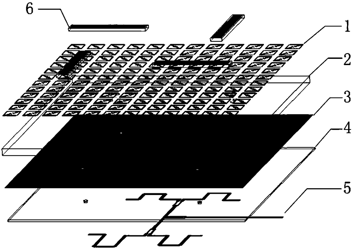
[0028] refer to figure 1 , figure 2

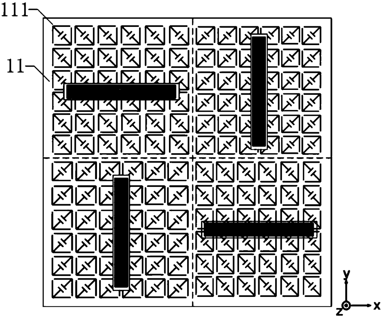
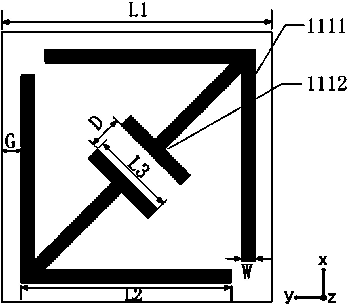
[0029] A low radar cross section array antenna based on polarization conversion, comprising a polarization conversion metasurface 1 and a first dielectric plate 2 printed on the lower surface of the polarization conversion metasurface 1, printed under the first dielectric plate 2 The metal floor 3 on the surface; the lower surface of the metal floor 3 is provided with a second dielectric plate 4 and a feed network 5 on the lower surface of the second dielectric plate 4, and the polarization conversion metasurface 1 is composed of four square polarization conversion unit groups 11 and N polarization conversion units 111 arranged periodically, wherein, N≥4, N is a positive integer, the upper surface of the four square polarization conversion metasurface unit groups 11 is provided with a pair connected to the feed network The pole 6 is characterized in that a pair of "L"-shaped metal patches 1111 of the same structure and a pair of "T"-sha...

Embodiment 2

[0041] This embodiment has the same structure as Embodiment 1, only some parameters have been adjusted:

[0042] The side length of the "L"-shaped metal patch 1111 of the polarization conversion unit 111 is L2 = 4.2 mm, and the side length of one end of the "T"-shaped metal patch 1112 is L3 = 0.8 mm. The polarization conversion metasurface 1 and the metal floor 3 The height dimension is H=1.9mm.

Embodiment 3

[0044] This embodiment has the same structure as Embodiment 1, only some parameters have been adjusted:

[0045] The side length of the "L"-shaped metal patch 1111 of the polarization conversion unit 111 is L2=4.6mm, and the side length of one end of the "T"-shaped metal patch 1112 is L3=1.2mm. The polarization conversion metasurface 1 and the metal floor 3 The height dimension is H=2.3mm.

[0046] Below in conjunction with simulation experiment, technical effect of the present invention is described further:

[0047] 1. Simulation conditions and content:

[0048] 1.1 Using the commercial simulation software HFSS_15.0 to simulate the reflection coefficient of the polarization conversion unit in the above example 1 in the range of 5GHz-35GHz, the results are as follows Figure 5 shown.

[0049] 1.2 Use the commercial simulation software HFSS_15.0 to simulate the polarization conversion rate of the polarization conversion unit in the above example 1 in the range of 5GHz-35GHz...


PUM

PropertyMeasurementUnit
Height dimensionaaaaaaaaaa

Abstract

The invention provides a low radar cross section array antenna based on polarization conversion. The antenna comprises a polarization conversion supersurface, a first dielectric plate printed on a lower surface of the polarization conversion supersurface, and a metal floor printed on a lower surface of the first dielectric plate. A second dielectric plate and a feed network on the low surface of the second dielectric plate are arranged on the low surface of the metal floor. The polarization conversion supersurface is composed of four square polarization conversion unit groups and N polarization conversion units arranged periodically. Each polarization conversion supersurface unit is composed of a pair of L-shaped metal patches located at the edge of the polarization conversion unit and T-shaped metal patches located in the center of the polarization conversion unit, the patches being of the same structure. The facing ends of the T-shaped metal patches are parallel to each other, and opposite ends of the T-shaped metal patches are connected to the right angles of the two respective L-shaped metal patches. The low radar cross section array antenna is high in polarization conversion rate within the broadband and solves the technical problems of the reduced radar cross section and the narrow bandwidth in the prior art.

Description

technical field [0001] The invention belongs to the field of communication technology, and specifically relates to a low radar cross-section array antenna based on polarization conversion. Using a polarization conversion metasurface structure, the radar cross-section of the antenna is reduced by controlling the reflected wave amplitude and phase characteristics, which can be applied to radiation characteristics Radar systems that have requirements for both radar and scattering characteristics. Background technique [0002] In today's communication field, the antenna, as a device for transmitting and receiving signals, is an important part of the entire communication system. With the development of wireless technology, the electromagnetic environment in which the radar antenna is located is becoming more and more complex. As a communication device, its radar cross section is an important contributor to the overall radar cross section of the target. The scattering of the ante...

Claims


Application Information

Patent Timeline
IPC IPC(8): H01Q1/36H01Q1/38H01Q1/50H01Q21/00
CPCH01Q1/36H01Q1/38H01Q1/50H01Q21/00
Inventor 洪涛王帅刘铮艳赵哲民彭可龚书喜
Owner XIDIAN UNIV
Why Eureka
Try Eureka