Eureka AIR delivers breakthrough ideas for toughest innovation challenges, trusted by R&D personnel around the world.

A method for determining the value range of the 3rd harmonic current of the distributed power flow controller

A technology of power flow controller and value range, applied in AC network circuits, circuit devices, AC networks with the same frequency from different sources, etc. The output efficiency of the flow device, etc.

Active Publication Date: 2022-03-04
WUHAN UNIV OF TECH
View PDF7 Cites 0 Cited by
  • Summary
  • Abstract
  • Description
  • Claims
  • Application Information

AI Technical Summary

Problems solved by technology

The 3rd harmonic current is generated by the single-phase converter on the parallel side of DPFC, which will generate 3rd harmonic voltage drop and 3rd harmonic loss on the transformer and line
The extra loss will not only increase the heating of the line to limit the transmission capacity of the line, but also reduce the output efficiency of the single-phase converter on the parallel side; the 3rd harmonic voltage drop on the line is added to the neutral point of the transformer, when it is higher than the transformer When the neutral point insulation voltage level is high, it will accelerate the aging of the transformer insulation and cause direct damage to it

Method used


Image

  • A method for determining the value range of the 3rd harmonic current of the distributed power flow controller
  • A method for determining the value range of the 3rd harmonic current of the distributed power flow controller
  • A method for determining the value range of the 3rd harmonic current of the distributed power flow controller

Examples


Embodiment Construction

[0077] One, at first introduce the method principle of the present invention.

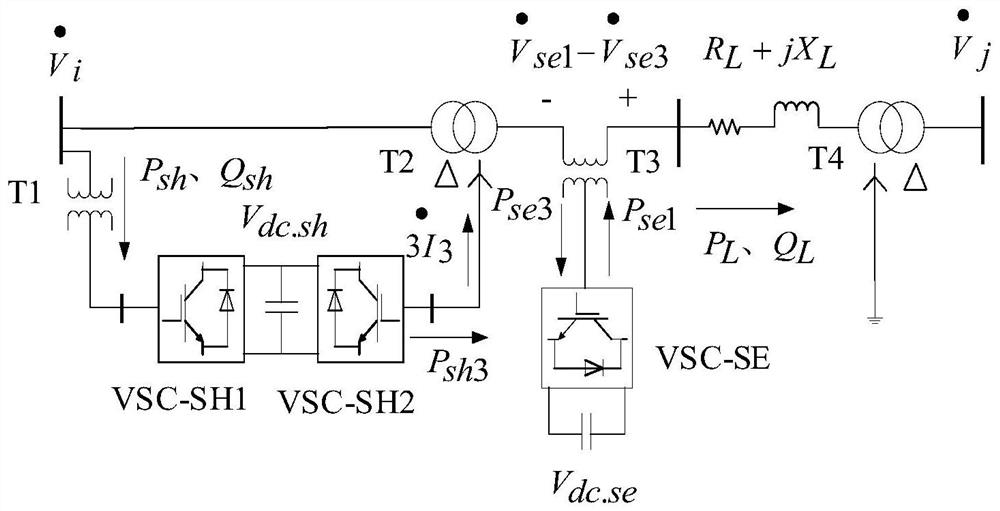
[0078] figure 1 It is the equivalent diagram of the DPFC device when there is only one series-side converter.

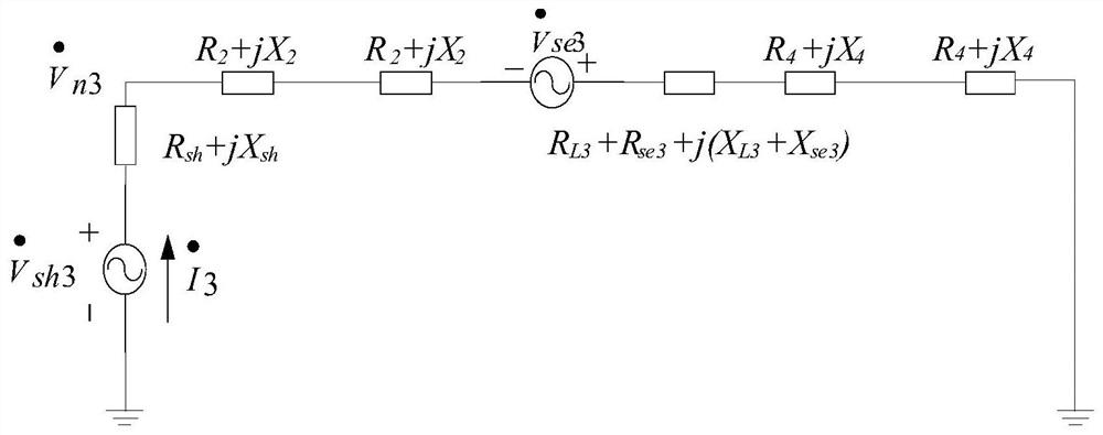
[0079] Among them, the access point bus voltage is The bus voltage at the end of the line is R L +jX L is the line impedance on the series side, P L , Q L is the active and reactive power at the outlet of DPFC. The working principle of DPFC is that the three-phase converter VSC-SH1 on the parallel side passes through the three-phase transformer T 1 Injecting reactive power into the busbar -Q sh To increase the access bus voltage the magnitude of . At the same time absorb active power P from the bus sh As a single-phase converter VSC-SH2 on the parallel side, the 3rd harmonic current is emitted The active source, VSC-SH2 via Δ-Y transformer T 2 3rd harmonic current from neutral point After flowing through the series side converter and the line, it finally passes through ...


PUM


Abstract

The invention belongs to the technical field of smart grid operation and stability control. It specifically relates to a method for determining the value range of the third harmonic current of a distributed power flow controller, so as to ensure the safe, stable and economical operation of a system including a distributed power flow controller. The third harmonic current is an important parameter to realize the function of distributed power flow controller. The present invention proposes the mathematical relationship between the 3rd harmonic current and the transmission capacity of the transmission line, the neutral point insulation voltage of the transformer on the parallel side, and the 3rd harmonic output efficiency of the single-phase converter on the parallel side, etc. The method of harmonic current value range provides a theoretical basis and reference for device parameter design.

Description

technical field [0001] The invention belongs to the technical field of smart grid operation and stability control. It specifically relates to a method for determining the value range of the third harmonic current of a distributed power flow controller, so as to ensure the safe, stable and economical operation of a system including a distributed power flow controller. Background technique [0002] Distributed Power Flow Controller (DPFC) has the advantages of low voltage level, low power, high redundancy, small investment and more powerful functions. It is realized by energy exchange on the parallel side. The 3rd harmonic current is generated by the single-phase converter on the parallel side of DPFC, which will generate 3rd harmonic voltage drop and 3rd harmonic loss on the transformer and line. The extra loss will not only increase the heating of the line to limit the transmission capacity of the line, but also reduce the output efficiency of the single-phase converter on...

Claims


Application Information

Patent Timeline
Patent Type & Authority Patents(China)
IPC IPC(8): H02J3/06
CPCH02J3/06H02J2203/20
Inventor 唐爱红卢智键曾涤非徐秋实郑旭洪梅子易柏年黄涌张述元
Owner WUHAN UNIV OF TECH
Why Eureka
Eureka Blog
Learn More