Method for operating motor vehicle brake system with anti-lock braking system and device for carrying out method

An anti-lock braking system, a technology for motor vehicles, applied in the direction of brakes, etc., can solve the problems of high braking pressure, increased NVH value roughness, etc., and achieve the effect of simple implementation

Inactive Publication Date: 2018-12-11
FORD GLOBAL TECH LLC
View PDF5 Cites 0 Cited by
  • Summary
  • Abstract
  • Description
  • Claims
  • Application Information

AI Technical Summary

Problems solved by technology

[0006] Additionally, the ABS actuator must build up brake pressure to prevent individual wheels from locking up, which can be problematic at high brake pre

Method used


Image

  • Method for operating motor vehicle brake system with anti-lock braking system and device for carrying out method

Examples


Embodiment Construction

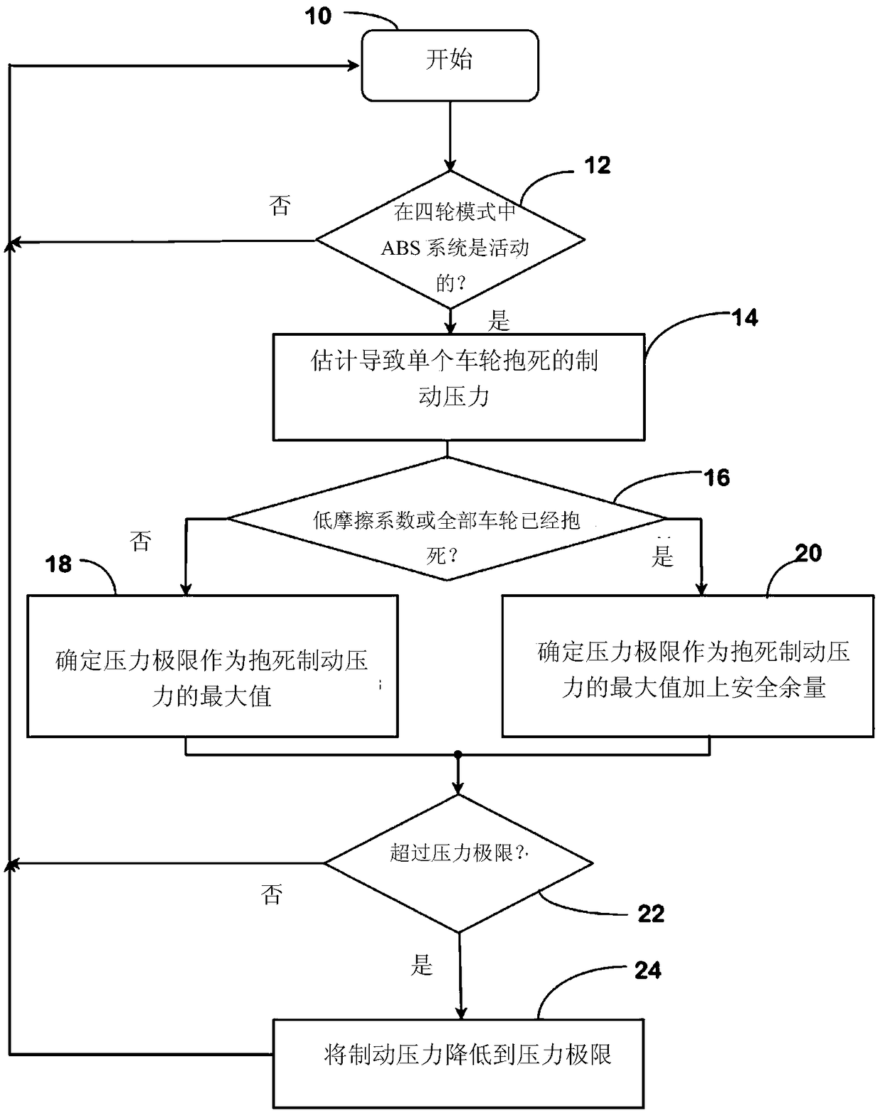
[0030] This method is usually implemented as a background loop in the case of microprocessor-based brake controllers. Individual steps of the method can—if technically meaningful—thus be omitted, replaced by other steps or their sequence changed.

[0031] After the start 10 of the method, in a step 12 it is queried whether the braking system is in ABS mode for all four wheels. If not, the process waits until the condition exists. Of course, the program can also be implemented as part of the corresponding four-wheel ABS control program and can be called up in the same way; query 12 would then be superfluous.

[0032] Alternatively, it is conceivable to use the invention in other states where a limitation of the brake pressure is foreseen, for example in certain ESP states.

[0033] If a four-wheel ABS mode is present, then in step 14 the brake pressures that will cause the wheels of each of the four wheels to lock are estimated. For this purpose, in the case of ABS control, ...


PUM


Abstract

A method for operating a hydraulic motor vehicle brake system with an anti-lock braking system is provided. The hydraulic motor vehicle brake system has a plurality of brake cylinders associated withwheels to be braked and a central pressure generating device for generating hydraulic brake pressure, wherein the hydraulic brake pressure is distributed to the brake cylinders and can be selectivelyreduced by performing ABS intervention on an individual brake cylinder or a group of brake cylinders, and the application of the anti-lock braking system effective for all wheels limits the pressure of the central pressure generating device. A pressure limit value, when a low coefficient of friction is detected or when all wheels are locked in a current ABS braking event, is set to be the calculated current maximum pressure value that would cause all wheels to lock plus a safety margin (20), otherwise, is set to be the current maximum pressure value without safety margin (18).

Description

technical field [0001] The invention relates to a method for operating a motor vehicle braking system with an anti-lock braking system and a mechanism for carrying out the method. Background technique [0002] Motor vehicle braking systems are known in different designs. Anti-lock braking systems (ABS) are currently part of the Electronic Stability Program (ESP), which is now mandatory for new vehicles in the European Union. The development of braking systems is currently changing from the classic hydraulic dual-circuit braking system with tandem master brake cylinder and hydraulic brake booster to electrically assisted braking systems or even brake-by-wire (BBW), where electrically There is no longer any mechanical or hydraulic connection between the brake pedal and the brakes in the brake system or brake-by-wire system. The last-mentioned system can in principle have a greater influence on the braking system used by the motor vehicle control system. [0003] During heav...

Claims


Application Information

Patent Timeline
IPC IPC(8): B60T8/176
CPCB60T8/1764B60T8/176B60T8/17616
Inventor 托马斯·斯文森
Owner FORD GLOBAL TECH LLC
Why Eureka
Try Eureka