Over-constrained shear fork-type double-layer annular truss deployable antenna mechanism

A ring-shaped truss, over-constrained technology, applied in the direction of folding antennas, retractable units, etc., can solve problems such as economic loss, winding, and antenna stiffness reduction, and achieve the effect of reducing manufacturing cost and difficulty, simple implementation, and relatively large folding

Active Publication Date: 2016-12-21
河北科讯通信器材有限公司
View PDF3 Cites 8 Cited by
  • Summary
  • Abstract
  • Description
  • Claims
  • Application Information

AI Technical Summary

Problems solved by technology

[0003] The ring-shaped truss-type deployable antenna has the characteristics of large folding ratio, small mass, and the mass does not increase proportionally with the increase of the aperture. It is an ideal structural form for large-diameter deployable antennas with tens of meters to hundreds of meters in space. Relevant scientific research in various countries People have conducted in-depth research on it, and achieved in-orbit applications, but there are few types of existing ring truss mechanisms, and there is a problem that the antenna stiffness decreases with the increase of the antenna diameter. Some ring trusses can be expanded The antenna adopts the tension zipper to improve the overall rigidity of the antenna mechanism, but the tension zipper is more complicated and difficult to control, which also reduces the reliability of the overall structure. During the deployment process, it is very easy to get entangled, which makes the deployment of the ring truss antenna fail, resulting in huge economic loss

Method used


Image

  • Over-constrained shear fork-type double-layer annular truss deployable antenna mechanism
  • Over-constrained shear fork-type double-layer annular truss deployable antenna mechanism
  • Over-constrained shear fork-type double-layer annular truss deployable antenna mechanism

Examples


Embodiment Construction

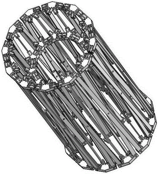
[0030] exist figure 1 , figure 2 , image 3 with Figure 4 In the schematic diagram of the deployable antenna mechanism of the over-constrained scissor double-layer ring truss, it includes the inner ring truss assembly (such as Figure 5 shown) outer ring truss components (such as Image 6 shown) and 2N inner and outer connecting truss assemblies C; the inner ring truss assembly includes N inner layer folding units A, each inner layer folding unit has the same structure, and the adjacent inner layer folding units pass through The two shared inner faceplates are connected to form an inner ring truss assembly, which is a multi-faceted ring truss structure after being expanded and folded; the outer ring truss assembly includes N outer folding units B, The structure of each outer layer folding unit is exactly the same, and the adjacent outer layer folding units are connected by sharing two outer layer faceplates to form an outer layer ring truss assembly, and the outer layer ...


PUM


Abstract

The invention relates to an over-constrained shear fork-type double-layer annular truss deployable antenna mechanism. The over-constrained shear fork-type double-layer annular truss deployable antenna mechanism comprises an inner-layer annular truss assembly, an outer-layer annular truss assembly and 2N inner and outer-layer connection truss assemblies; the inner-layer annular truss assembly includes N inner-layer folding and unfolding units; adjacent inner-layer folding and unfolding units are connected with each other through two common inner-layer disc chucks, so that the inner-layer annular truss assembly can be formed; the outer-layer annular truss assembly includes N outer-layer folding and unfolding units; adjacent folding and unfolding units are connected with each other through two common outer-layer disc chucks, so that the outer-layer annular truss assembly can be formed; and two inner-layer disc chucks at the upper part and lower part of the same side of each of inner-layer folding and unfolding units are connected with four outer-layer disc chucks of a certain outer-layer folding and unfolding unit through two inner and outer-layer connection truss assemblies, so that the shear fork-type double-layer annular truss deployable antenna mechanism can be formed. The shear fork-type double-layer annular truss deployable antenna mechanism of the invention has good manufacturing process, high rigidity and large folding ratio.

Description

technical field [0001] The invention relates to a deployable antenna mechanism. Background technique [0002] With the continuous development of the aerospace industry, the size of space mechanisms required in various aerospace projects is getting larger and larger to meet the needs of different space missions. The application of space large-aperture antennas can greatly improve the level of earth observation resolution, satellite communication distance and data transmission capacity, space power generation capabilities, space reconnaissance and precision strike capabilities, etc., and its development has always been highly valued by countries all over the world. An important application of the large-scale space deployment mechanism in the aerospace field is as a deployment and support mechanism for large-aperture antennas. Currently, the large-aperture space-deployable antennas that have been successfully developed mainly include expandable rib antennas, frame-type deployab...

Claims


Application Information

Patent Timeline
Patent Type & Authority Applications(China)
IPC IPC(8): H01Q1/10
CPCH01Q1/10
Inventor 赵永生韩博许允斗姚建涛刘文兰韩家旭吴宇
Owner 河北科讯通信器材有限公司
Why Eureka
Try Eureka