
Impurity removal device for river sewage

A technology for sewage and rivers, applied in water/sewage multi-stage treatment, water/sludge/sewage treatment, flocculation/sedimentation water/sewage treatment, etc., can solve problems such as poor practicability, high use limitations, and filter blockage , to achieve the effect of reducing the limitation of use, improving the reliability of use and improving the practicality

Inactive Publication Date: 2018-12-11
SUZHOU BLUE KING MACHINE TOOL TECH CO LTD
View PDF0 Cites 1 Cited by
  • Summary
  • Abstract
  • Description
  • Claims
  • Application Information

AI Technical Summary

Problems solved by technology

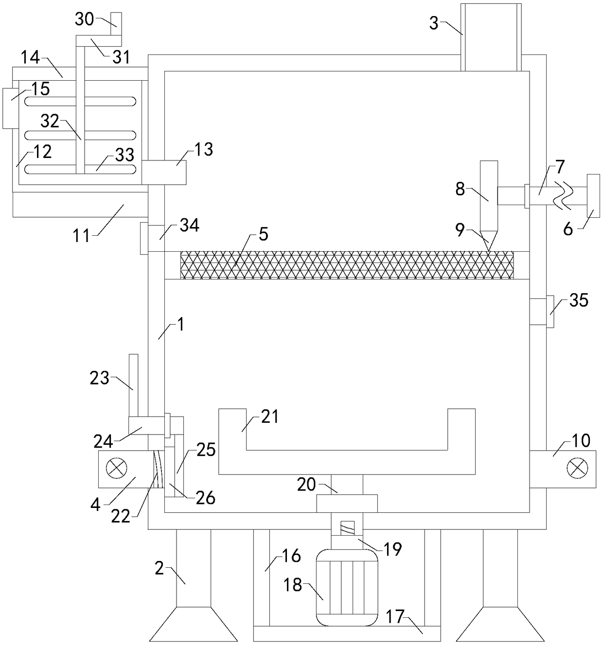
[0002] As we all know, the river sewage removal device is an auxiliary device used in the river sewage treatment process to remove impurities and make it better for reuse. It has been widely used in the field of river sewage removal ; The existing river sewage removal device includes a working box and four groups of supports, and the tops of the four groups of supports are installed on the left front side, the right front side, the left rear side and the right rear side of the bottom of the working box respectively, and a working chamber is arranged in the working box. A feed pipe is connected to the right side of the top of the work box, a discharge pipe is connected to the lower left side of the work box, and a discharge valve is set at the discharge pipe, and a filter is installed inside the work box; the existing river sewage removal When the miscellaneous device is used, the river sewage is introduced into the working chamber from the feed pipe, filtered through the filter, and discharged through the discharge pipe; it is found in the use of the existing river sewage removal device that the filter cannot be blocked when the filter is blocked. It is convenient to dredge, resulting in poor reliability of use; and the odor of river sewage cannot be easily adsorbed, resulting in high limitations in use; and its overall realization of functions is less, resulting in poor practicability

Method used


Image

  • Impurity removal device for river sewage
  • Impurity removal device for river sewage

Examples


Embodiment Construction

[0013] The specific implementation manners of the present invention will be further described in detail below in conjunction with the accompanying drawings and embodiments. The following examples are used to illustrate the present invention, but are not intended to limit the scope of the present invention.

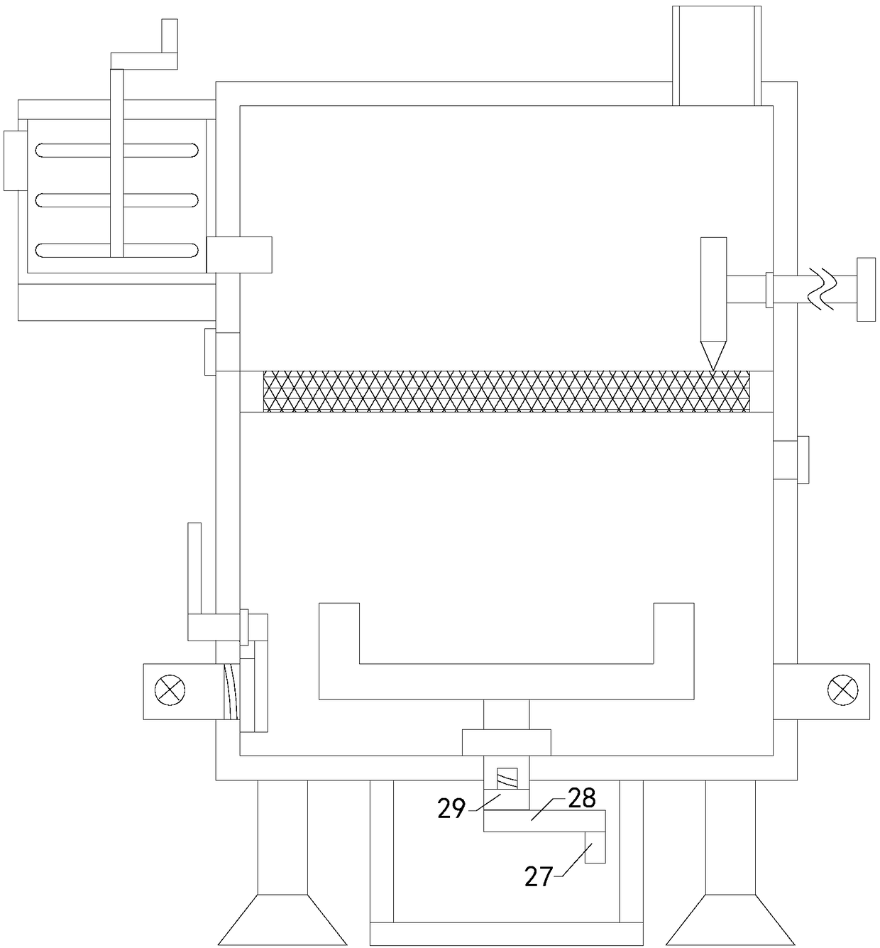
[0014] Such as figure 1 and figure 2 As shown, a river sewage removal device of the present invention comprises a working box 1 and four groups of supports 2, and the tops of the four groups of supports are respectively installed on the left front side, right front side, left rear side and right rear side of the bottom end of the working box. There is a working chamber inside the box, a feed pipe 3 is connected to the top right side of the work box, a discharge pipe 4 is connected to the bottom left side of the work box, and a discharge valve is arranged at the discharge pipe. Filter screen 5; also comprises push plate 6, push rod 7, push block 8 and scraper 9, and push...


PUM


Abstract

The invention relates to the technical field of impurity removal auxiliary devices for river sewage and in particular relates to an impurity removal device for river sewage. The impurity removal device comprises a working box and four groups of brackets, wherein the working box is internally provided with a working cavity; the right side of the top end of the working box is communicated with a feeding pipe; the lower side of the left side of the working box is communicated with a discharging pipe; a discharging valve is arranged on the discharging pipe; a filtering screen is arranged in the working box; the impurity removal device further comprises a push plate, a push rod, a push block and a scraping plate; a first sealing ring sleeves the outer side of the push rod; the lower side of theright side of the working box is communicated with a gas feeding pipe; the device further comprises a supporting platform, an adsorption box and a communication pipe; an adsorption cavity is arrangedin the adsorption box; the top end of the adsorption box is communicated with a replacement opening; a cover plate is arranged at the replacement opening; adsorption carbon is placed in the adsorption cavity; the upper side of a left side wall of the adsorption box is communicated with an exhausting fan; and the device further comprises two groups of supporting columns, a supporting plate, a motor, a first connection rod, a transmission shaft and stirring blades and a second sealing ring sleeves the outer side of the transmission shaft.

Description

technical field [0001] The invention relates to the technical field of an accessory device for removing impurities in river sewage, in particular to a device for removing impurities in river sewage. Background technique [0002] As we all know, the river sewage removal device is an auxiliary device used in the river sewage treatment process to remove impurities and make it better for reuse. It has been widely used in the field of river sewage removal ; The existing river sewage removal device includes a working box and four groups of supports, and the tops of the four groups of supports are installed on the left front side, the right front side, the left rear side and the right rear side of the bottom of the working box respectively, and a working chamber is arranged in the working box. A feed pipe is connected to the right side of the top of the work box, a discharge pipe is connected to the lower left side of the work box, and a discharge valve is set at the discharge pipe...

Claims


Application Information

Patent Timeline
Patent Type & Authority Applications(China)
IPC IPC(8): C02F9/04B01D53/06
CPCC02F1/001B01D53/06B01D2253/102C02F1/52C02F2103/007C02F2303/16
Inventor 孙生强
Owner SUZHOU BLUE KING MACHINE TOOL TECH CO LTD
Learn More