
Rotating shaft limiting device

A technology of limiting device and rotating shaft, which is applied to bridge parts, bridges, buildings, etc., can solve the problems of falling beam damage, failure of anti-falling beam stopper, lack of contact, etc., to reduce maintenance work, save time and cost of construction Effect

Inactive Publication Date: 2018-12-11
SHENYANG JIANZHU UNIVERSITY
View PDF0 Cites 0 Cited by
  • Summary
  • Abstract
  • Description
  • Claims
  • Application Information

AI Technical Summary

Problems solved by technology

However, due to the lack of connection between the beam body and the pier body, and between the beam body and the beam body, when a high-intensity earthquake strikes, under the impact of the violent shaking of the beam body, the anti-fall beam stoppers are prone to shear failure and fail, resulting in fall beam failure

Method used


Image

  • Rotating shaft limiting device
  • Rotating shaft limiting device
  • Rotating shaft limiting device

Examples


Embodiment Construction

[0022] In order to further illustrate the present invention, the present invention will be described in detail below in conjunction with the accompanying drawings and embodiments, but they should not be construed as limiting the protection scope of the present invention.

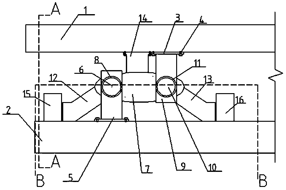
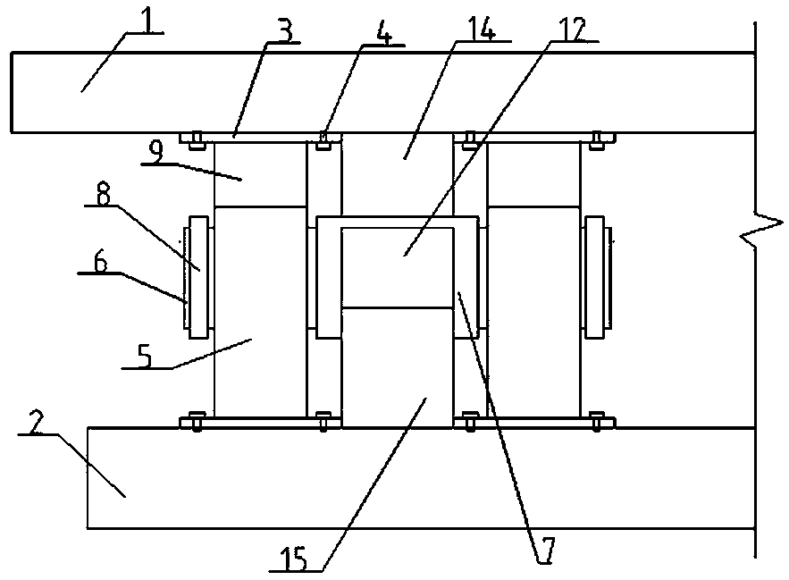
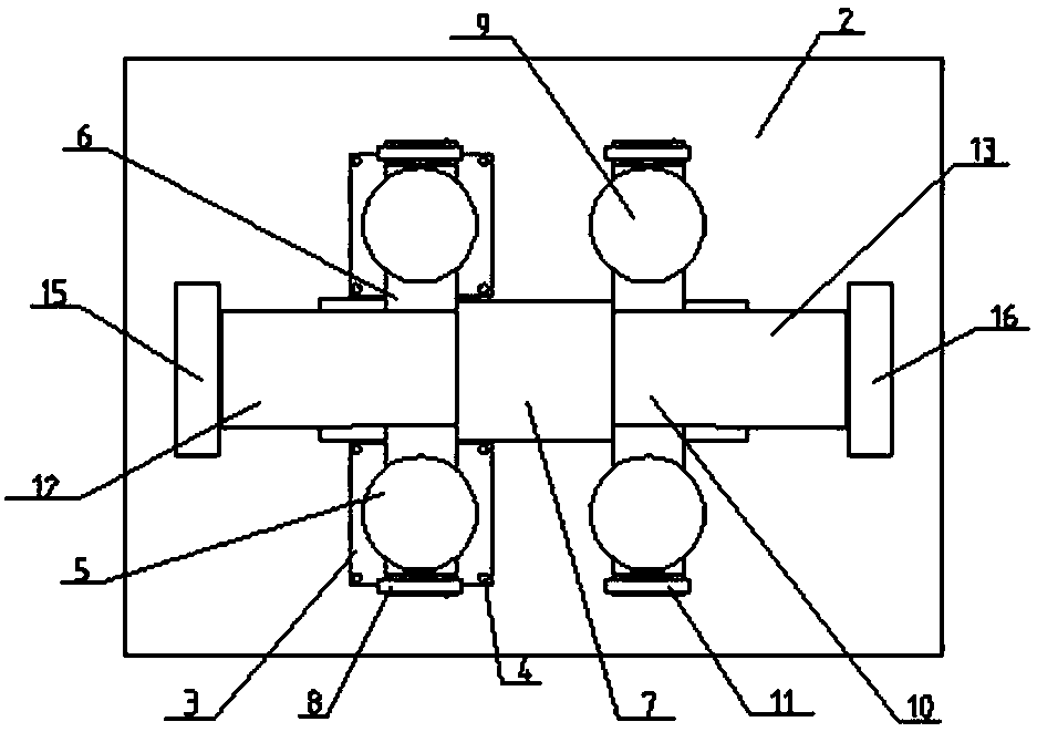
[0023] Such as Figure 1-3 As shown, a rotating shaft type limiting device of the present invention includes a bridge deck 1, a pier 2, a connecting plate 3, a connecting bolt 4, a supporting lower rod 5, a front bearing 6, a turntable 7, a front nut 8, a supporting upper rod 9, Rear bearing 10, rear nut 11, front foot support 12, rear foot support 13, top support 14, front foot support limit 15 and rear foot support limit 16, and a connecting plate 3 is respectively set at a distance of 40-50 cm from the left and right edges of the bridge deck bottom , the top surface of the connecting plate of the bridge deck is in close contact with the bottom surface of the bridge deck 1, and at the four corners of the c...


PUM


Abstract

The invention discloses a rotating shaft limiting device, wherein a connecting plate is arranged on the bottom surface of the bridge deck, a through hole arranged in the side wall of the right supportupper bar, and a rotary disc arranged at the left side wall of an upper rod of the right support rod by 3-4 cm, upper rods of a left support arranged on the left side of the rotary disc by 3-4 cm. left and right support upper rods are respectively connected with the bottom surface of a connecting plate on the bridge deck of the corresponding side, and the top support is welded with the center ofthe top surface of the rotary table; A link plate is arrange on that top surface of the bridge pier, The connecting plate is tightly attached to the pier and fixed by connecting bolts. The left and right supporting lower bars are symmetrically positioned on both sides of the rotary table. The front and rear foot supports are composed of horizontal bars and diagonal bars. The diagonal bars supported by the front and rear feet are respectively connected with the front and rear bearings. The horizontal bars are tightly attached to the pier. The front and rear foot support limits are respectivelypositioned at the front and rear foot support horizontal bar top ends by 1-2cm. The invention has the advantages of simple structure, reduced maintenance work after earthquake and prolonged bridge service life.

Description

technical field [0001] The invention belongs to the technical field of building construction, and in particular relates to a rotating shaft type limiting device. Background technique [0002] With the rapid development of our country's transportation construction, bridges, as the hub projects on the transportation line, are growing rapidly both in number and in extension length. And my country is an earthquake-prone country, and once bridges are damaged by falling beams in an earthquake, the entire transportation network will be paralyzed. [0003] The seismic design of bridges in my country mainly emphasizes the strength of the pier, how to prevent the pier from collapsing in an earthquake. The anti-fall beam structure adopted is mainly to fix the anti-fall beam stoppers on the pier to control the longitudinal displacement and lateral displacement of the beam within a certain range. However, due to the lack of connection between the beam body and the pier body, and betwee...

Claims


Application Information

Patent Timeline
Patent Type & Authority Applications(China)
IPC IPC(8): E01D19/00
CPCE01D19/00
Inventor 张延年高忠慧吴献
Owner SHENYANG JIANZHU UNIVERSITY
Learn More