
Bottom fixation stabilizer for utility poles

A bottom fixing and stabilizing device technology, which is applied in the direction of building types, buildings, towers, etc., can solve problems such as dumping, limited depth of insertion, and danger, and achieve the effects of improving safety, prolonging service life, and improving installation stability

Inactive Publication Date: 2018-12-11
宁夏爱打听科技有限公司
View PDF4 Cites 4 Cited by
  • Summary
  • Abstract
  • Description
  • Claims
  • Application Information

AI Technical Summary

Problems solved by technology

[0002] Telephone poles are the most common electrical equipment, as long as they are electrified, they can be seen. Most of the existing telegraph poles are simple straight rods inserted into the lower end of the ground. Sometimes, due to the limited depth of insertion, they are prone to tipping over when subjected to external forces. , causing danger

Method used


Image

  • Bottom fixation stabilizer for utility poles
  • Bottom fixation stabilizer for utility poles
  • Bottom fixation stabilizer for utility poles

Examples


Embodiment 1

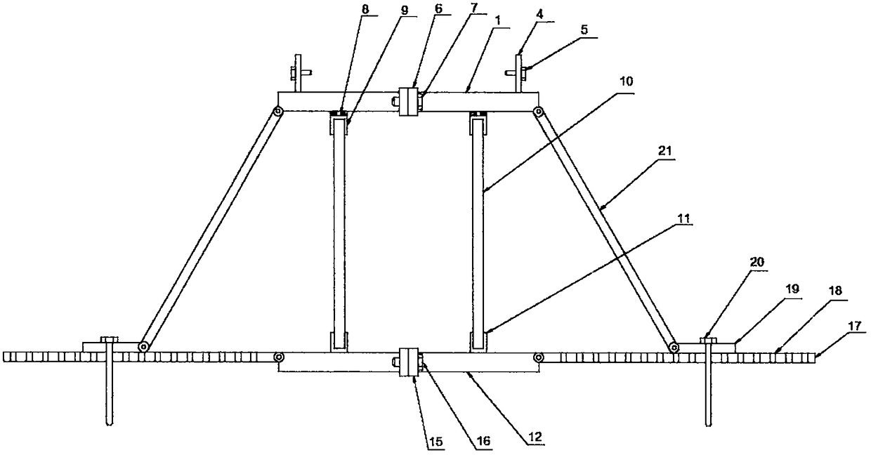
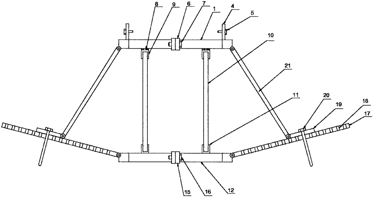
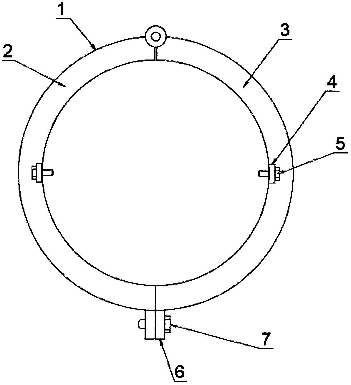
[0023] Such as Figure 1-4 The shown stabilizing device for fixing the bottom of a utility pole includes a first fixing ring 1, and the first fixing ring 1 includes a first half ring 2 and a second half ring 3, and the first half ring 2 and the second half ring The second half-ring 3 is provided with a fixing plate 4, the fixing plate 4 is provided with a first screw 5, and the first connecting plate 6 is provided at the connection between the first half-ring 2 and the second half-ring 3, so that The first connecting plate 6 is provided with a second screw 7, the bottom of the first fixing ring 1 is provided with a connecting bearing 8, and the bottom of the connecting bearing 8 is provided with a first bushing 9, and the first bushing 9 The bottom end is provided with a first connecting rod 10, and the bottom end of the first connecting rod 10 is provided with a second sleeve 11, and the bottom end of the second sleeve 11 is provided with a second fixing ring 12, and the seco...

Embodiment 2

[0026] Such as Figure 1-4 In the shown stabilizer for fixing the bottom of a utility pole, the first half ring 2 and the second half ring 3 are hinged, the side wall of the fixing plate 4 is coplanar with the inner wall of the first fixing ring 1, and the second half ring The number of one connecting plate 6 is set to two, and the first half ring 2 and the second half ring 3 are detachably connected through the first connecting plate 6 and the first screw 5 .

[0027] The outer ring of the connecting bearing 8 is fixedly connected to the bottom of the first fixed ring 1, the inner ring of the connecting bearing 8 is fixedly connected to the first sleeve 9, and the first sleeve 9 is connected to the first fixed ring 1 through the connecting bearing 8. Flexible connection, the outer wall of the first connecting rod 10 is provided with threads, the top end of the first connecting rod 10 is detachably connected with the first sleeve 9 through threads, and the bottom end is detach...


PUM


Abstract

The invention discloses a bottom fixation stabilizer for utility poles, which comprises a first fixing ring including a first half ring and a second half ring; each of the first and second half ringsis provided with a fixing plate; a first screw is passed through each fixing plate; a first connection plate is arranged at the joint of the first and second half rings; a second screw is passed through the first connection plate; a connection bearing is arranged at the bottom of the first fixing ring; a first sleeve is arranged at the bottom of the connection bearing. The first fixing ring is fixedly connected with a utility pole via the first screws and the fixing plates; the first fixing ring and a second fixing ring are connected via first connection rods, first sleeve and second sleeves;the first fixing ring and the second fixing ring are supported via a plurality of second connection rods and second connection plates; therefore, the utility pole in the first and second fixing ringsis mounted more stably, with better safety.

Description

technical field [0001] The invention relates to the field of electric power auxiliary devices, in particular to a stabilizing device for fixing the bottom of an electric pole. Background technique [0002] Telephone poles are the most common electrical equipment, as long as they are electrified, they can be seen. Most of the existing telegraph poles are simple straight rods inserted into the lower end of the ground. Sometimes, due to the limited depth of insertion, they are prone to tipping over when subjected to external forces. , causing danger. [0003] Therefore, it is necessary to invent a stabilizing device for fixing the bottom of the utility pole to solve the above problems. Contents of the invention [0004] The object of the present invention is to provide a stabilizing device for fixing the bottom of an electric pole. By using the first screw and the fixing plate to fix the first fixing ring and the electric pole, the first connecting rod, the first sleeve and ...

Claims


Application Information

Patent Timeline
Patent Type & Authority Applications(China)
IPC IPC(8): E04H12/22
CPCE04H12/22E04H12/2215
Inventor 陶晶
Owner 宁夏爱打听科技有限公司
Learn More