Device and method for detachable manual assembling steel column

A dismantling, steel column technology, applied in the field of construction equipment, can solve the problems of affecting railway traffic safety, inconvenient disassembly and installation, waste of manpower, etc., to achieve the effect of improving construction efficiency and construction quality, facilitating disassembly and installation, and saving manpower

Pending Publication Date: 2018-12-11
中铁十四局集团电气化工程有限公司
View PDF0 Cites 1 Cited by
  • Summary
  • Abstract
  • Description
  • Claims
  • Application Information

AI Technical Summary

Problems solved by technology

[0004] Although the erection of steel columns is often realized with the help of electric equipment, in many construction environments, it is still necessary to manually assemble the steel columns, such as station yards and along railway lines, because the concrete foundation is exposed to the ground and the ground The foot bolts are higher than the foundation, and they are usually assembled manually and with a crane
When lifting with a crane, the stability of the steel column is poor during the erection process, which is not conducive to safe construction and easily affects the safety of railway traffic
For example, in the construction environment of some mountainous terrain, large equipment is difficult to enter, and in such cases, the steel column assembly work can only be completed manually
[0005] The deficiencies of the existing artificial erection of steel columns: First, the construction of artificial steel column erection is limited by surrounding environmental factors
On plateaus with permafrost, such as the environment and geological conditions of my country's Qinghai-Tibet line, it is difficult for lifting equipment to enter the site, the labor intensity is high, the project cost is high, and the ecological environment of the construction site is easily damaged
If the emergency repair steel column is fixed at the bottom during the assembly period, there may be collapse, landslide, subsidence, etc., which will cause the steel column to intrude and directly endanger the safety of railway traffic; The lifting method of the equipment, the connection between the steel column foot and the concrete foundation bolt is rough, and it is easy to bend and damage the thread of the bolt and cause personal unsafe accidents; third, the existing steel column assembly construction, its assembly structure and process are cumbersome and wasteful Manpower, high efficiency and low cost, not easy to disassemble and install in the field

Method used


Image

  • Device and method for detachable manual assembling steel column
  • Device and method for detachable manual assembling steel column
  • Device and method for detachable manual assembling steel column

Examples


Embodiment 1

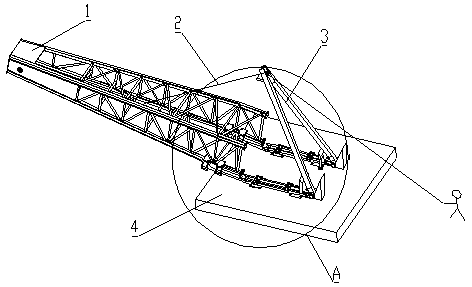
[0053] see Figure 1 to Figure 7 According to the needs of on-site construction, steel columns are divided into various models according to length and capacity, mainly including G200-13, G250-13, G250-15, G300-15, G350-15, G450-15 and other models. The weight of the steel column has the greatest impact on the construction of the steel column assembly. The weight of the steel column is summarized in the table below according to the Tonghua diagram.

[0054]

[0055]

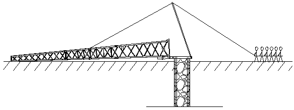
[0056] The main device of manual steel erection adopts a detachable design. After the construction personnel arrive at the site, they will install the artificial steel column erection device and prepare for steel column erection. Manual erection of steel columns at the construction site such as figure 1 shown.

[0057] According to the actual situation of the artificial steel column erection site, the mechanical analysis of the mathematical model of the artificial erection steel column construction is carr...

Embodiment 2

[0108] On the basis of Embodiment 1, the support 3 is an inverted V-shaped support; the support 3 includes two straight rods, the upper ends of the two straight rods are fixedly connected to the vertical parts on both sides of a U-shaped ring, and the middle part of the U-shaped ring is provided with scroll wheel;

[0109] The side of the bracket 3 facing the steel column 1 is provided with a boss 31, the boss 31 is arranged on the lower side of the top of the bracket 3, and the angle between the upper surface of the boss 31 and the upper part of the bracket 3 is 60°. The boss 31 can be used to push the bracket 3 to rotate by pushing the boss 31 if the steel column 1 may touch the bracket 3 when it stands up. And because of the function of the boss 31, it can prevent the sling 2 from being caught by the steel column 1 and the bracket 3 and cause jamming. At the same time, the angle between the boss 31 and the bracket 31 is more helpful for the steel column 1 to push the bracke...

Embodiment 3

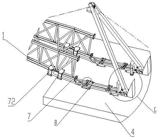
[0112] On the basis of Embodiment 1 or 2, the stopper 73 of the connecting part 7 is provided with a turning roller. The axis of the rotating roller is perpendicular to the direction in which the connecting part 7 rotates, and the effect of the rotating roller is to make it slide down from the stopper 73 more easily when the steel column stands up.


PUM


Abstract

The invention discloses a device and a method for a detachable manual assembling steel column, and relates to the field of building equipment. A technical scheme is that the device comprises a steel column base used to place a steel column and a support, and the middle part of the steel column is bound with one end of a sling. The sling crosses the top of the support. A free end of the sling is held by hand of a constructor. The steel column base is fixedly provided with a base. One end of the base, far away from the support, is hinged with one end of a connecting component. The other end of the connecting component is fixedly connected with the lower outer side of the steel column. An included angle between the side surface of steel column, facing the steel column, and a horizontal planeis larger than or equal to 30 DEG and is smaller than or equal to 90 DEG. Beneficial effects are that the structure connection form is used in the device, and the device is suitable for assembly of steel columns in different specifications and shapes. The steel column is hinged and connected with the base through the connecting component. Using the structure ensures structural mechanical properties of a connection position, and related standards and use requirement are satisfied.

Description

technical field [0001] The invention relates to the field of construction equipment, in particular to a detachable device and method for manually erecting steel columns. Background technique [0002] The main contents of the steel column erection construction are: the lower part and the upper part, and the upper part includes the connection between the steel column and the concrete foundation. The steel column and concrete foundation are used to bear the full load of the contact suspension, supporting and positioning devices, and fix the contact suspension at the specified position and height. The concrete foundation is for the steel column, that is, the steel column is fixed on the concrete foundation made of reinforced concrete below, and the concrete foundation bears all the load transmitted by the steel column and ensures the stability of the steel column. [0003] In order to ensure the smooth progress of the artificial erection of steel columns, it is necessary to hav...

Claims


Application Information

Patent Timeline
Patent Type & Authority Applications(China)
IPC IPC(8): E04H12/34
CPCE04H12/345
Inventor 汪培平张凤杰谭祥雷张涛
Owner 中铁十四局集团电气化工程有限公司
Why Eureka
Try Eureka