Eureka AIR delivers breakthrough ideas for toughest innovation challenges, trusted by R&D personnel around the world.

Liquid velocity controllable valve for liquid hydrogen storage tank

A flow rate control and storage tank technology, which is applied in the field of liquid hydrogen storage tanks, can solve the problems of inconvenient liquid hydrogen transportation and inaccurate transportation, and achieve the effects of preventing liquid hydrogen backflow, accurate delivery volume, and ease of use

Inactive Publication Date: 2018-12-11
HANGZHOU LANJIE HYDROGEN ENERGY TECH CO LTD
View PDF5 Cites 2 Cited by
  • Summary
  • Abstract
  • Description
  • Claims
  • Application Information

AI Technical Summary

Problems solved by technology

[0004] The purpose of the present invention is to provide a liquid flow rate controllable valve for liquid hydrogen storage tanks, which solves the defects that the existing valves cannot accurately transport liquid hydrogen and are not convenient for liquid hydrogen transport.

Method used

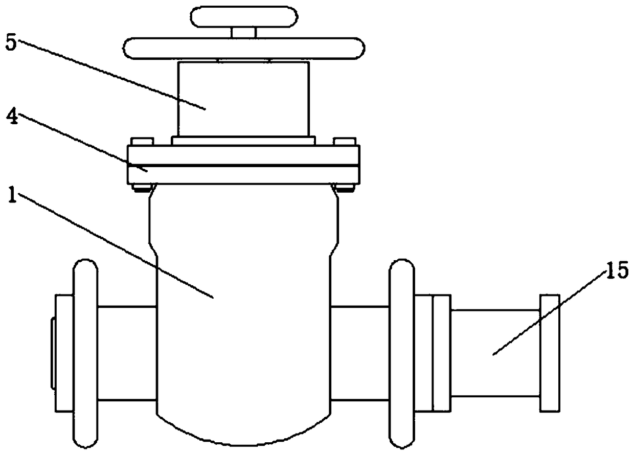

Image

  • Liquid velocity controllable valve for liquid hydrogen storage tank
  • Liquid velocity controllable valve for liquid hydrogen storage tank
  • Liquid velocity controllable valve for liquid hydrogen storage tank

Examples


Embodiment Construction

[0019] The technical solutions in the embodiments of the present invention will be clearly and completely described below in conjunction with the embodiments of the present invention. Obviously, the described embodiments are only a part of the embodiments of the present invention, rather than all the embodiments. Based on the embodiments of the present invention, all other embodiments obtained by those of ordinary skill in the art without creative work shall fall within the protection scope of the present invention.

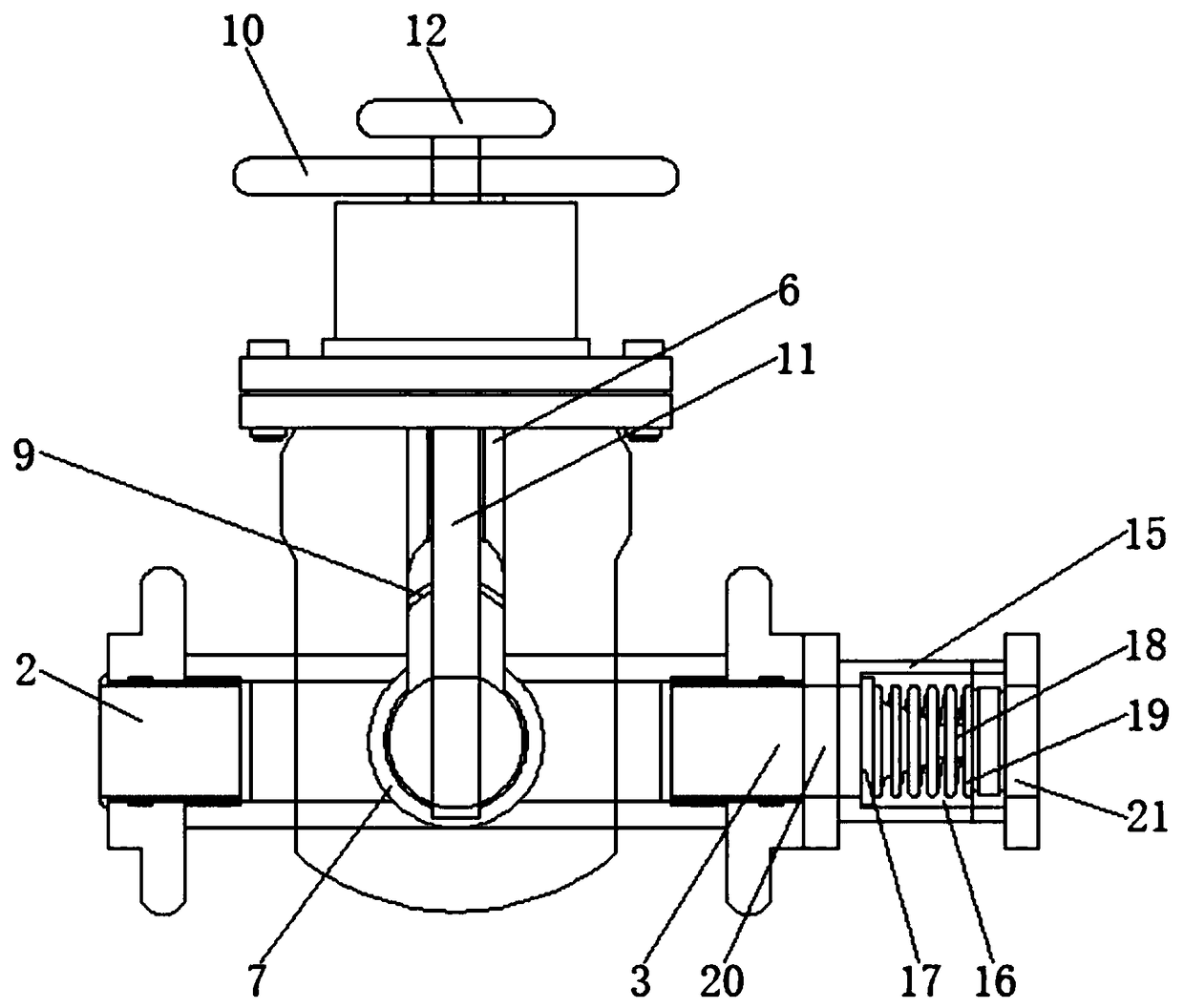
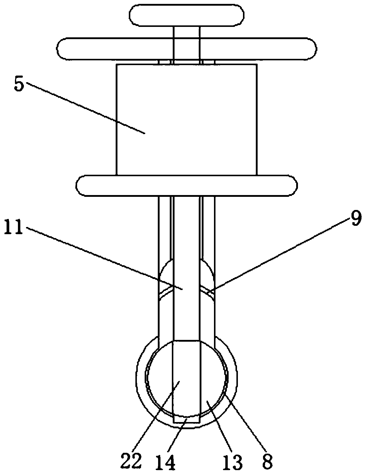
[0020] Such as Figure 1-3 As shown, a liquid flow controllable valve for a liquid hydrogen storage tank includes a valve body 1, a first liquid inlet 2 is opened on the left side of the valve body 1, and a right side of the valve body 1 is opened For the first liquid outlet 3, a flange 4 is fixedly connected to the top of the valve body 1, and a valve core 5 is embedded and fixedly installed in the flange 4, and a first valve stem 6 is embedded and installed in the...


PUM


Abstract

The invention discloses a liquid velocity controllable valve for a liquid hydrogen storage tank. The liquid velocity controllable valve for the liquid hydrogen storage tank comprises a valve body; a first liquid inlet is formed in the left side face of the valve body; a first liquid outlet is formed in the right side face of the valve body; a flange is fixedly connected to the top of the valve body; a valve element is fixedly installed in the flange in an embedded mode; a first valve rod is installed in the valve element in an embedded mode; the lower end of the first valve rod is inserted inthe valve body; a liquid barrier ball is fixedly installed on the lower surface of the first valve rod and provided with a spherical through hole; a sealing ring is fixedly installed at the position,at the upper end of the liquid barrier ball, of the first valve rod; and a first velocity control hand shank is fixedly installed on the top of the first valve rod. According to the liquid velocity controllable valve for the liquid hydrogen storage tank, the speed of liquid hydrogen flowing through the valve can be controlled through a second velocity control hand shank, a second valve rod and a velocity control baffle, workers can use the valve conveniently, the liquid hydrogen can be effectively prevented from flowing back by means of a backflow prevention pipe during adjustment of the liquid hydrogen velocity, and thus the valve has higher practicability.

Description

Technical field [0001] The invention belongs to the technical field of liquid hydrogen storage tanks, in particular to a liquid flow rate controllable valve for liquid hydrogen storage tanks. Background technique [0002] Liquid hydrogen is a liquid obtained by cooling hydrogen gas. It is a colorless, odorless, high-energy, low-temperature liquid fuel. The normal boiling point of hydrogen at one atmospheric pressure is 20.37K (-252.78°C) and the freezing point is 13.96K (-259.19°C). The density is 70.85kg / m3. Liquid hydrogen is one of the main storage methods of hydrogen. [0003] At present, the practical valves in liquid hydrogen storage tanks are not only complex in structure, but also simple in function. In the transportation of fluids in the existing storage tanks, the valves installed on them only have functions such as cutoff, diversion, and diversion, and they cannot The flow rate of hydrogen is controlled, so that the liquid hydrogen cannot be accurately transported duri...

Claims


Application Information

Patent Timeline
Patent Type & Authority Applications(China)
IPC IPC(8): F16K1/22F16K17/04F17C13/04
CPCF16K1/22F16K17/04F17C13/04Y02E60/32Y02P90/45
Inventor 韦达
Owner HANGZHOU LANJIE HYDROGEN ENERGY TECH CO LTD
Why Eureka
Eureka Blog
Learn More