Vibration reduction type rotating joint structure

A technology of rotary joints and rotary sleeves, which is applied in the direction of pipes/pipe joints/fittings, adjustable connections, passing components, etc. It can solve the problems of shell impact force, no vibration damping performance, and affecting the service life of rotary joints, so as to improve the use of long life, good vibration damping performance, and easy operation

Active Publication Date: 2018-12-11
杭州优能特旋转接头精密制造有限公司
View PDF13 Cites 0 Cited by
  • Summary
  • Abstract
  • Description
  • Claims
  • Application Information

AI Technical Summary

Problems solved by technology

Since the shell of the rotary joint is usually static, and the rotating parts are connected to the external rotating pipeline, the external pipeline will inevitably vibrate when it rotates at high speed, so that the radial movement between the rotating parts in the rotary joint and the shell of the rotary joint will occur. Generally, there is a sealing ring between the rotating parts in the rotary joint and the outer shell, and the sealing ring can be used for small radial runouts. However, the axial fit between the rotating parts and the outer shell is tight, so it cannot produce Relative displacement, so the axial runout cannot be overcome. When the rotating parts rotate, a large axial vibration force will be generated between the shells, which will generate a frequent impact force on the shell, which will reduce the overall use of the rotary joint life
[0003] For example: Chinese Patent Application Publication No. CN105793631A discloses a rotary joint, and Chinese Patent Application Publication No. CN104279385A discloses a high-tight rotary joint. None of them has vibration damping performance. When the rotating parts vibrate, they will frequently collide with the shell, which will seriously affect the service life of the rotary joint.

Method used


Image

  • Vibration reduction type rotating joint structure
  • Vibration reduction type rotating joint structure
  • Vibration reduction type rotating joint structure

Examples


Embodiment Construction

[0025] The present invention will be further described below in conjunction with accompanying drawing and specific embodiment:

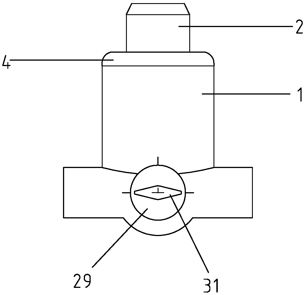
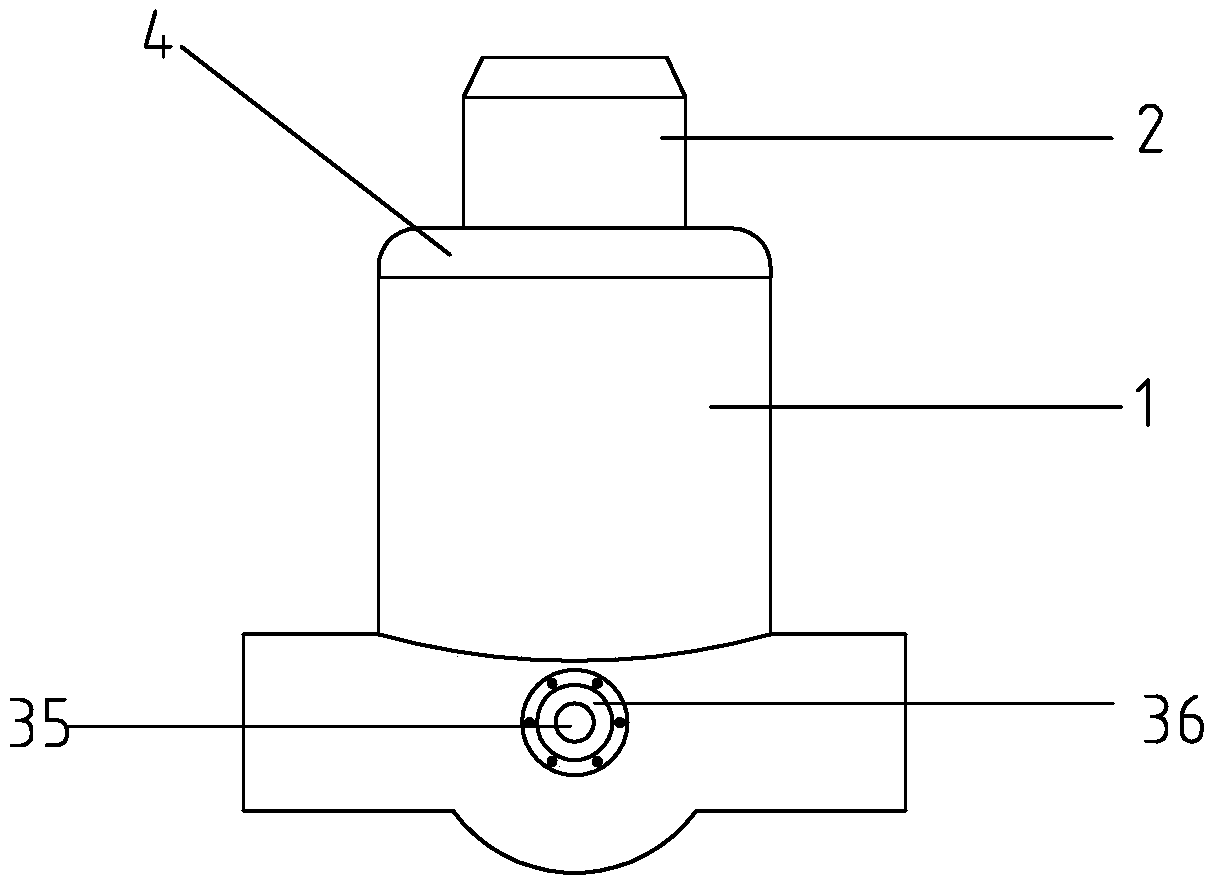
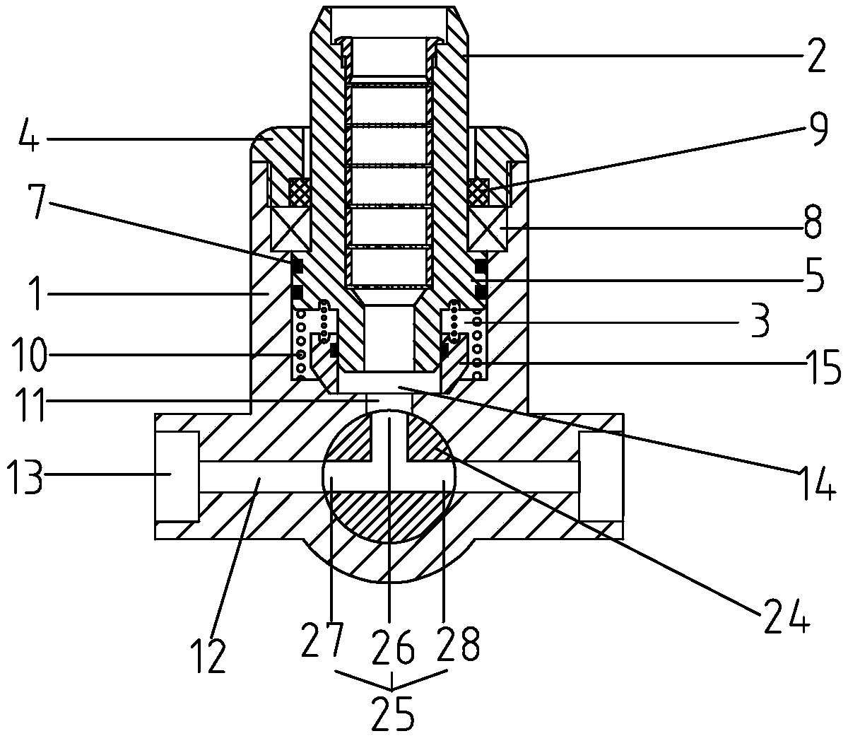
[0026] Such as figure 1 , figure 2 and image 3 The structure of a vibration-damping rotary joint shown includes a housing 1 and a rotating sleeve 2. The upper end of the housing is provided with a rotating cavity 3. The lower end of the rotating sleeve extends into the rotating cavity, and the upper end of the rotating sleeve extends out of the joint body. , the opening end of the rotating cavity is provided with an end cap 4, and the outer side of the rotating sleeve is provided with a limiting protruding ring 5, which forms a clearance fit with the rotating cavity, and the circumferential surface of the limiting protruding ring is provided with an annular groove 6, and the annular groove There is a sealing ring A7 inside; a bearing 8 is provided between the upper end of the limiting convex ring and the end cover, and a dustproof retaining ring ...


PUM


Abstract

The invention relates to the technical field of rotating joints, and discloses a vibration reduction type rotating joint structure. The vibration reduction type rotating joint structure comprises a housing and a rotating sleeve; a rotating cavity is formed at the upper end of the housing; the lower end of the rotating sleeve stretches into the rotating cavity; the upper end of the rotating sleevestretches out of a joint body; an end cover is arranged at the open end of the rotating cavity; a limiting bulge loop is arranged on the outer side of the rotating sleeve; the limiting bulge loop is in clearance fit with the rotating cavity; an annular groove is formed in the circumference surface of the limiting bulge loop; a sealing ring A is arranged in the annular groove; a bearing is arrangedat the part between the upper end of the limiting bulge loop and the end cover; a pressure spring is arranged between the lower end of the limiting bulge loop and the bottom surface of the rotating cavity; a guide hole is formed in the center of the bottom surface of the rotating cavity; a liquid outlet channel transversely penetrating is formed in the lower end of the housing; the side surfacesof the middles of the guide hole and the liquid outlet channel are penetrated; and interfaces are formed in the two ends, located at the liquid outlet channel, of the housing. The vibration reductiontype rotating joint structure has good vibration reduction performance and can alleviate axial and radial vibration effectively, and the entire service life is prolonged.

Description

technical field [0001] The invention relates to the technical field of rotary joints, in particular to a vibration-damping rotary joint structure. Background technique [0002] The rotary joint is a connecting part, which is used to transfer the medium from the static pipeline to the rotary pipeline, especially in metallurgy, ship lifting, chemical industry, pharmaceutical and other industries. A rotary joint needs to be installed between the two rotating pipelines to realize the rotary connection of the pipelines. Since the shell of the rotary joint is usually static, and the rotating parts are connected to the external rotating pipeline, the external pipeline will inevitably vibrate when it rotates at high speed, so that the radial movement between the rotating parts in the rotary joint and the shell of the rotary joint will occur. To and axial runout, usually a sealing ring is provided between the rotating parts in the rotary joint and the casing, the sealing ring can be...

Claims


Application Information

Patent Timeline
IPC IPC(8): F16L27/08
CPCF16L27/0804
Inventor 李勇
Owner 杭州优能特旋转接头精密制造有限公司
Why Eureka
Try Eureka