
Selective laser melting additive manufacturing method and additive manufacturing device for manganese-copper alloy forming

A laser selective melting, manganese-copper alloy technology, applied in the field of additive manufacturing, can solve the problems of difficult forming process of additive manufacturing, easy volatilization of manganese to form holes and cracks, no forming quality, etc., to improve mechanical properties and damping performance, The effect of comprehensive mechanical properties and damping performance, good vibration reduction and damping performance

Active Publication Date: 2020-10-13
飞而康快速制造科技有限责任公司
View PDF4 Cites 4 Cited by
  • Summary
  • Abstract
  • Description
  • Claims
  • Application Information

AI Technical Summary

Problems solved by technology

The laser forming process of different materials is quite different. At present, the additive manufacturing technology has been applied to a large extent in the fields of TC4 titanium alloy, stainless steel, superalloy, aluminum alloy and other materials. However, compared with the traditional manufacturing technology, the application of additive manufacturing There are still few types of materials in the technology, and the laser additive manufacturing forming process of materials is the key to the application of this technology. At present, for manganese-copper alloys, because they contain more manganese, manganese is easy to volatilize under the action of lasers in the forming process to form holes and cracks. The forming process of additive manufacturing is difficult, and there is no SLM forming process with good forming quality at present

Method used


Image

  • Selective laser melting additive manufacturing method and additive manufacturing device for manganese-copper alloy forming
  • Selective laser melting additive manufacturing method and additive manufacturing device for manganese-copper alloy forming
  • Selective laser melting additive manufacturing method and additive manufacturing device for manganese-copper alloy forming

Examples


Embodiment 1

[0074] The injector damping ring of M2052 manganese-copper alloy is prepared by using the additive manufacturing device provided in the specific embodiment, and the content of each element in the M2052 manganin-copper alloy used is shown in the following table:

[0075] element mn Cu Ni Fe Impurities Content [wt%] 63.15 26.85 5.2 3.8 margin

[0076] The specific additive manufacturing process includes the following steps:

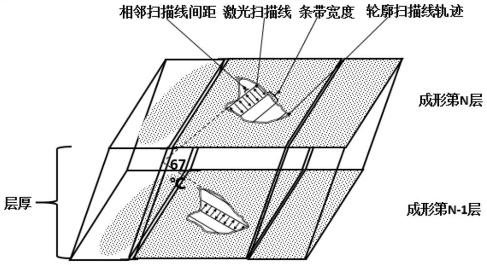
[0077] (1) Build a three-dimensional structural model of the target part, add an auxiliary support structure on the outer surface of the model, perform two-dimensional slice layering on the model, and import the model slice layer file into the additive manufacturing software to generate a slice scanning path;

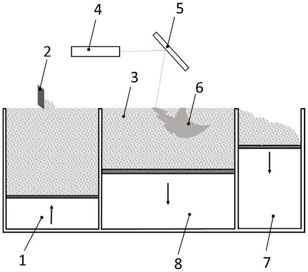
[0078] (2) The vertically movable partition in the powder supply cabin 1 moves up, and the M2052 manganese-copper alloy powder 3 stored in the powder supply cabin 1 is pushed out of the powder supply cabin 1. The av...

Embodiment 2

[0086] The injector damping ring of M2052 manganese-copper alloy is prepared by using the additive manufacturing device provided in the specific embodiment, and the content of each element in the M2052 manganin-copper alloy used is shown in the following table:

[0087] element mn Cu Ni Fe Impurities Content [wt%] 65.28 25.36 5.34 3.4 margin

[0088] The specific additive manufacturing process includes the following steps:

[0089] (1) Build a three-dimensional structural model of the target part, add an auxiliary support structure on the outer surface of the model, perform two-dimensional slice layering on the model, and import the model slice layer file into the additive manufacturing software to generate a slice scanning path;

[0090] (2) The vertically movable partition in the powder supply cabin 1 moves up, and the M2052 manganese-copper alloy powder 3 stored in the powder supply cabin 1 is pushed out of the powder supply cabin 1. The a...

Embodiment 3

[0098] The additive manufacturing device provided by the specific embodiment is used to prepare the submarine propeller of the M2052 manganese-copper alloy. The content of each element in the M2052 manganese-copper alloy used is shown in the following table:

[0099] element mn Cu Ni Fe Impurities Content [wt%] 71.32 20.45 5.2 2 margin

[0100] The specific additive manufacturing process includes the following steps:

[0101] (1) Build a three-dimensional structural model of the target part, add an auxiliary support structure on the outer surface of the model, perform two-dimensional slice layering on the model, and import the model slice layer file into the additive manufacturing software to generate a slice scanning path;

[0102] (2) The vertically movable partition in the powder supply cabin 1 moves up, and the M2052 manganese-copper alloy powder 3 stored in the powder supply cabin 1 is pushed out of the powder supply cabin 1. The average...


PUM

PropertyMeasurementUnit
bulk densityaaaaaaaaaa
particle diameteraaaaaaaaaa

Abstract

The invention provides a selective laser melting additive manufacturing method and additive manufacturing device for manganese-copper alloy forming. The method comprises the following steps that (I) scanning, melting and solidifying of a laser beam are carried out in a strip scanning manner along a slicing solid region of a constructed part model, and the laser technological parameters in the scanning, melting and solidification process are controlled; scanning, melting and solidifying are carried out along the outer contour line of a slice to obtain a part forming layer; (II) the manganese-copper alloy powder in a forming cabin moves downwards, the forming cabin is filled with the supplemented manganese-copper alloy powder, the laser melts and solidifies the titanium alloy powder again, and layer-by-layer accumulation is conducted till a complete formed part is formed; and (III) in the vacuum environment, the formed part is repeatedly subjected to at least two times of heat treatmentprocesses, each heat treatment process comprises heating, heat preservation and cooling which are sequentially carried out, and technological parameters of the heat treatment process are strictly controlled. Through strictly controlling laser process parameters and heat treatment process parameters, the mechanical property of an M2052 manganese-copper alloy structural member is improved.

Description

technical field [0001] The invention belongs to the technical field of additive manufacturing, and relates to an additive manufacturing method and an additive manufacturing device for selective laser melting, in particular to an additive manufacturing method and an additive manufacturing device for laser selective melting for manganese-copper alloy forming . Background technique [0002] Laser selective melting forming technology, as an implementation of additive manufacturing technology, is developed from powder bed selective laser sintering technology. Metal powder is used as processing raw material, and high-energy-density laser beams are used to spread the powder on the metal substrate layer by layer. Cladding is built up to form a manufacturing technique for metal parts. The basic principle is as follows: firstly, using slicing technology to discretize the continuous three-dimensional CAD digital model into layered slices with a certain layer thickness and order; secon...

Claims


Application Information

Patent Timeline
Patent Type & Authority Applications(China)
IPC IPC(8): B22F3/105B22F3/24B33Y10/00B33Y30/00
CPCB22F3/24B33Y10/00B33Y30/00B22F2003/248B22F2998/10Y02P10/25
Inventor 汪承杰
Owner 飞而康快速制造科技有限责任公司
Learn More