
Narrow ring gap heat exchange air conditioning terminal device

An air conditioner terminal and annular gap technology, which is applied in household heating, pipeline layout, household heating, etc., can solve the problems of low heat transfer coefficient, easy to produce blowing sensation, and can not bear the humidity load of air conditioner, so as to improve the heat transfer capacity , high heat transfer efficiency, and enhanced heat transfer effect

Active Publication Date: 2018-12-11
DALIAN UNIV OF TECH
View PDF5 Cites 1 Cited by
  • Summary
  • Abstract
  • Description
  • Claims
  • Application Information

AI Technical Summary

Problems solved by technology

The noise level of the fan coil unit is generally between 30dB-60dB, and the speed of the air outlet is between 2-4m / s, which is easy to produce a windy feeling, and is not suitable for occasions that require high noise control; Condensation is allowed on the surface, which not only limits the cooling capacity of the radiant panel, but also cannot bear the humidity load of the indoor air conditioner
In the patent "Wet Radiation Convective Cooling and Heat Exchanger" (ZL201410012986.4), aiming at the characteristics of low cooling / heating load of near-zero-energy buildings, it proposes a method that can satisfy both winter heating and summer cooling, and has The terminal equipment with dehumidification function, but because the heat exchange between the cold heat exchanger and the indoor environment is carried out through natural convection and radiation, the heat transfer coefficient is relatively low, so when the indoor load is large, the area of ​​the terminal equipment is required also larger

Method used


Image

  • Narrow ring gap heat exchange air conditioning terminal device
  • Narrow ring gap heat exchange air conditioning terminal device
  • Narrow ring gap heat exchange air conditioning terminal device

Examples


Embodiment Construction

[0028] The following will clearly and completely describe the technical solutions in the embodiments of the present invention with reference to the accompanying drawings in the embodiments of the present invention. Obviously, the described embodiments are only some, not all, embodiments of the present invention. Based on the embodiments of the present invention, all other embodiments obtained by persons of ordinary skill in the art without making creative efforts belong to the protection scope of the present invention.

[0029] The invention provides a narrow-gap heat exchange air conditioner terminal device, which can enhance the heat exchange effect and improve the heat exchange capacity of the air conditioner terminal device under the premise of ensuring that there is no obvious blowing sensation in the working area of ​​the personnel, and has both heating in winter and cooling in summer .

[0030] In order to make the above objects, features and advantages of the present i...


PUM


Abstract

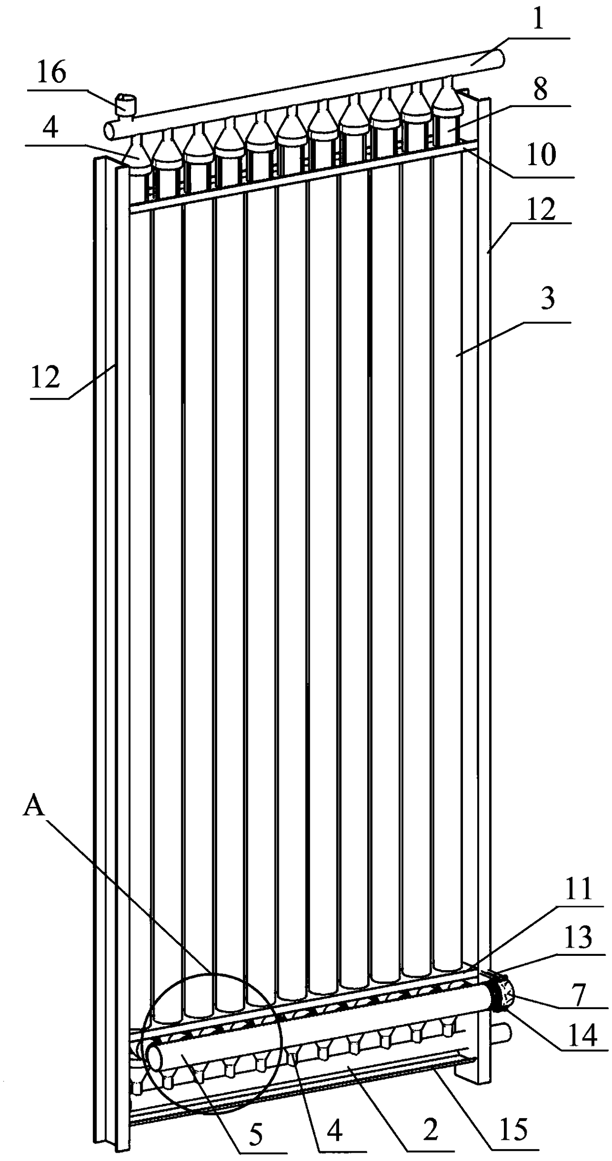
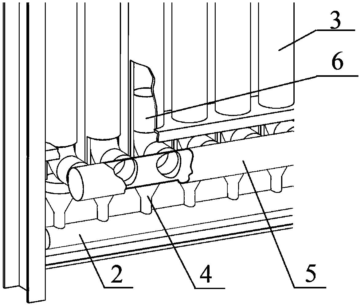
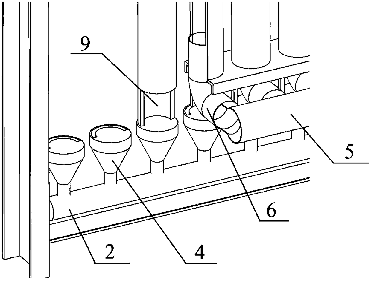
The invention discloses a narrow ring gap heat exchange air conditioning terminal device, and relates to the technical field of heating ventilation air conditioning system terminal devices. The terminal device comprises an installation frame, a water system and an air system; the water system comprises an upper header pipe, a lower header pipe and heat exchange pipes, and the multiple heat exchange pipes are vertically fixed to the installation frame; each heat exchange pipe comprises an inner pipe and an outer casing pipe, and the inner pipe is fixed in the outer casing pipe; a liquid flow channel is formed between each inner pipe and each outer casing pipe, and an air flow channel is formed in each inner pipe; the two ends of each liquid flow channel communicate with the upper header pipe and the lower header pipe separately; the air system comprises an air main pipe and a ducted fan connected to the air main pipe, and the air main pipe communicates with the air flow channel; and oneside of the top of each heat exchange pipe is provided with an upper air opening, and the air flow channel communicates with outside through the upper air opening. According to the terminal device, on the premise of ensuring that a working area of personnel has no obvious blowing feeling, the heat exchange effect can be improved, and the heat exchange capability of the air conditioning terminal device is improved; and the terminal device has the functions of heating in winter and cooling in summer.

Description

technical field [0001] The invention relates to the technical field of terminal devices of HVAC systems, in particular to a narrow-gap heat-exchanging air-conditioning terminal device. Background technique [0002] Nearly zero-energy buildings represent the development trend of future buildings with their characteristics of ultra-low energy consumption and high thermal comfort. The energy consumption of the HVAC system is the most important component of building energy consumption. In a near-zero energy building with low cooling / heating load as its important feature, the traditional HVAC system should also be adjusted accordingly. At present, the common air-conditioning terminal equipment that can realize both cooling and heating in buildings in my country mainly includes fan coil units and radiant panels. The noise level of the fan coil unit is generally between 30dB-60dB, and the speed of the air outlet is between 2-4m / s, which is easy to produce a sense of wind, and is n...

Claims


Application Information

Patent Timeline
Patent Type & Authority Applications(China)
IPC IPC(8): F24F13/00F24F13/02F24F13/30F24F13/32
CPCF24F13/00F24F13/02F24F13/30F24F13/32
Inventor 舒海文张宏亮姜珊
Owner DALIAN UNIV OF TECH
Learn More