Push-out type ice cube tray structure and refrigerator with push-out type ice cube tray structure

An ice-making tray and ejecting technology, which is applied to ice-making, ice-making, household refrigerators, etc., can solve the problems of inconvenient way of flipping and taking ice, ice cubes flying out, ice-making tray damage, etc.

Inactive Publication Date: 2018-12-11
HUBEI MIDEA REFRIGERATOR CO LTD
View PDF10 Cites 9 Cited by
  • Summary
  • Abstract
  • Description
  • Claims
  • Application Information

AI Technical Summary

Problems solved by technology

[0004] The object of the present invention is to provide a top-out type ice-making tray structure and a refrigerator with it, so as to solve the problem of turning over and taking ice from the ice-making tray in the existing ice machine in...

Method used


Image

  • Push-out type ice cube tray structure and refrigerator with push-out type ice cube tray structure
  • Push-out type ice cube tray structure and refrigerator with push-out type ice cube tray structure
  • Push-out type ice cube tray structure and refrigerator with push-out type ice cube tray structure

Examples


Embodiment 1

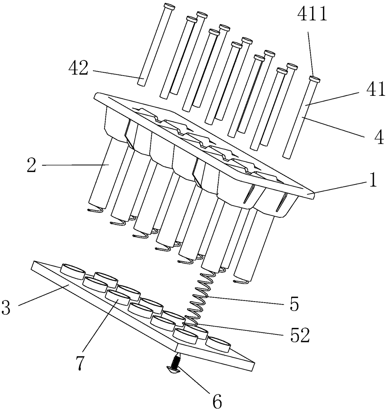
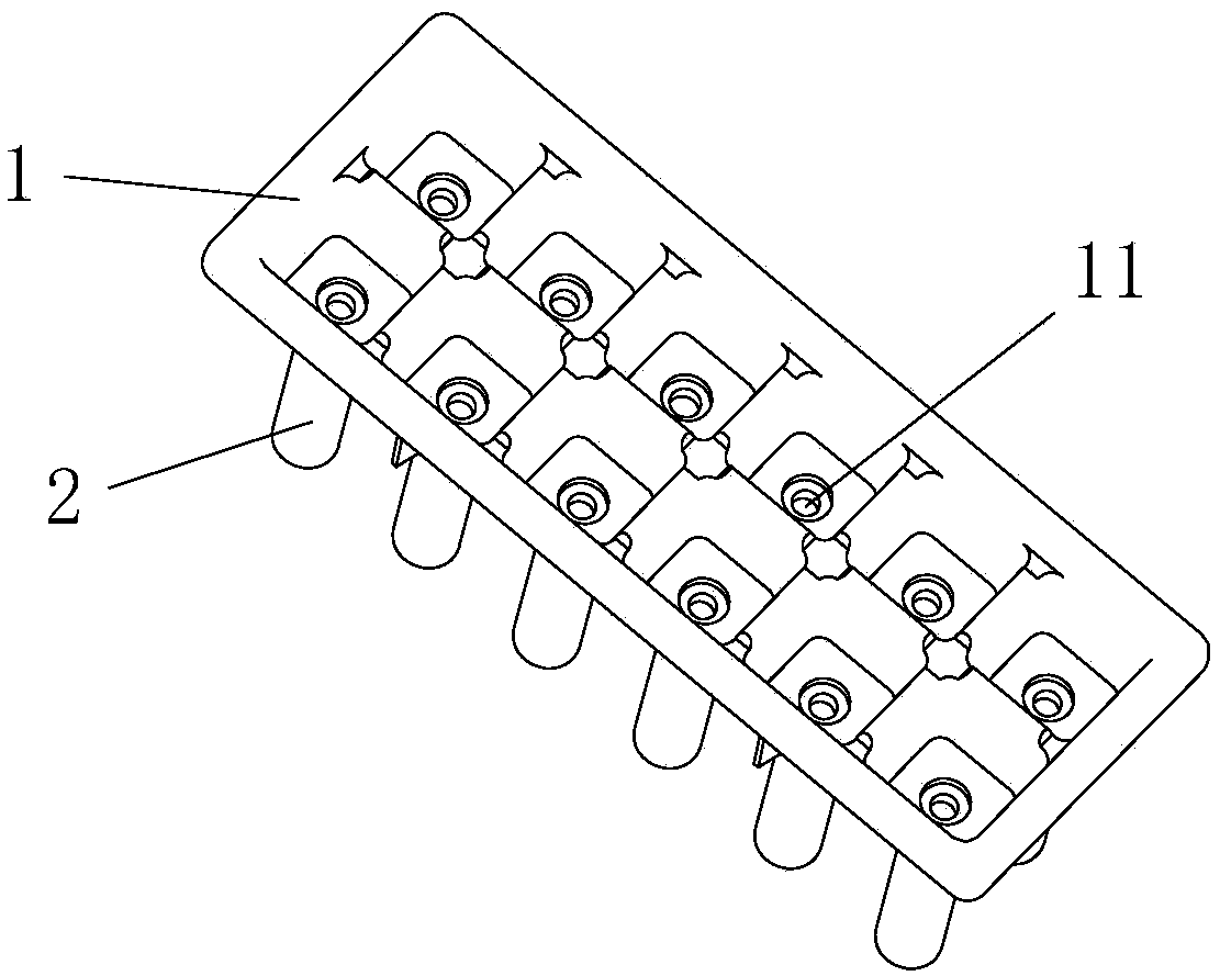
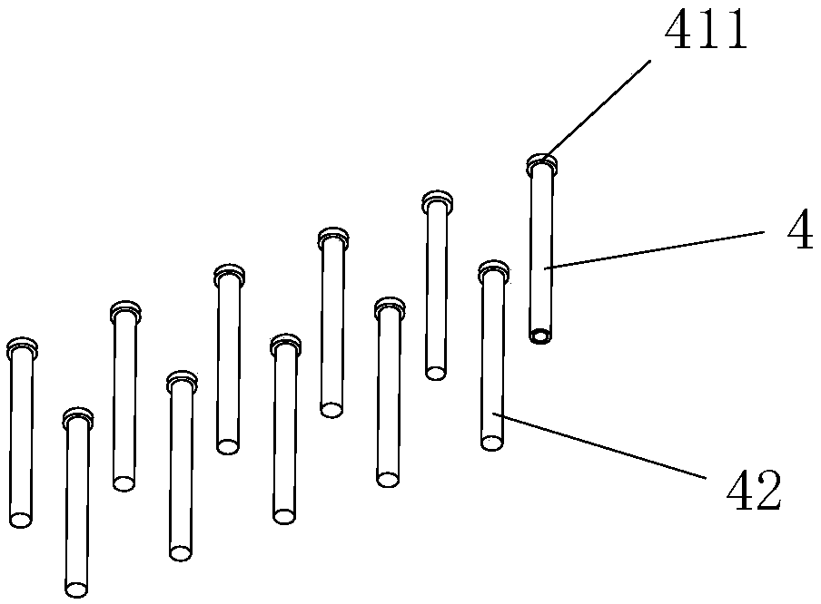
[0027] Such as Figure 1 to Figure 4 As shown, the figure schematically shows that the ejection ice-making tray structure includes an ice-making tray 1, a cylinder body 2, a bottom plate 3, an ejection member 4, and an elastic support member 5.

[0028] In the embodiment of the present application, a through hole 11 is configured on the bottom wall of the ice-making tray 1, and a cylindrical body 2 extending downward is configured on the edge of the through hole 11. It should be noted that the inner diameter of the through hole 11 is smaller than the inner diameter of the cylinder 2, so that the upper end of the cylinder 2 will be constructed with a shielding portion (constituted by the bottom wall of the ice tray 1), which is equivalent to The upper cover plate is arranged above the cylinder 2 and has a through hole.

[0029] The shape of the bottom plate 3 is not only limited to the rectangle shown in the figure, but can also be adjusted accordingly according to actual needs, su...

Embodiment 2

[0050] This embodiment is basically the same as Embodiment 1. For brevity of description, in the description process of this embodiment, the same technical features as Embodiment 1 will not be described, and only the differences between this embodiment and Embodiment 1:

[0051] According to the second aspect of the present application, there is also provided a refrigerator (not shown in the figure), including a freezing chamber and a refrigerating chamber, and further including the above-mentioned top-out ice tray structure provided in the freezing chamber.

[0052] In summary, by forming a through hole 11 on the bottom wall of the ice making tray 1, the above-mentioned cylinder 2 is configured on the edge of the through hole 11, and by installing the ejection member 4 in the cylinder 2, At the same time, the upper end of the ejection member 4 is made to block the through hole 11 to prevent water leakage during ice making. The lower end of the ejection member 4 is fixedly connected...


PUM


Abstract

The invention relates to the technical field of household appliance manufacturing and discloses a push-out type ice cube tray structure and a refrigerator with the push-out type ice cube tray structure. The push-out type ice cube tray structure comprises an ice cube tray, a base plate, a push-out part and an elastic support part, wherein a through hole is formed on a bottom wall of the ice cube tray; a barrel which extends downward is constructed on an edge of the through hole; the push-out part is arranged in the barrel; the through hole is plugged by the upper end of the push-out part; the lower end of the push-out part is fixedly connected with the base plate; the elastic support part is arranged between the barrel and the push-out part and is used for keeping the lower end of the barrel under a free suspending state; a first end of the elastic support part is resisted against the bottom wall of the ice cube tray; a second end of the elastic support part is resisted against the baseplate. The push-out type ice cube tray structure has the advantage that ice can be conveniently and quickly taken off.

Description

Technical field [0001] The invention relates to the technical field of household appliances manufacturing, in particular to a top-out ice-making tray structure and a refrigerator with the same. Background technique [0002] The refrigerator includes a freezer compartment and a refrigerating compartment. An ice maker is installed in the freezer. When taking ice from the ice making tray in the existing ice making machine, it is often necessary to flip the ice making tray to make the ice cubes fall out of the ice making tray. Sometimes, it is necessary to shake or twist the ice tray to make it deform, so as to achieve the purpose of ice removal. If the ice cube is connected to the ice tray too tightly, a tool must be used to lift the ice cube. However, the above-mentioned flipping ice taking method is very inconvenient to operate. Shaking the ice making tray to take ice can easily cause the ice cubes to fly out, and twisting the ice making tray until it is deformed to remove the ice...

Claims


Application Information

Patent Timeline
IPC IPC(8): F25C1/24F25D11/02
CPCF25C1/24F25D11/02
Inventor 王元章杨必发
Owner HUBEI MIDEA REFRIGERATOR CO LTD
Why Eureka
Try Eureka