
Gravity compound pendulum-based ultra-high precision micro force measuring device and measuring method

The technology of a measuring device and measuring method, which is applied in the field of ultra-high-precision micro-thrust measuring devices, can solve problems such as the influence of measuring accuracy, and achieve the effects of reducing vibration, simple structure of the measuring device, simple and easy-to-operate measuring principle and method

Active Publication Date: 2018-12-11
NANJING UNIV OF AERONAUTICS & ASTRONAUTICS
View PDF13 Cites 7 Cited by
  • Summary
  • Abstract
  • Description
  • Claims
  • Application Information

AI Technical Summary

Problems solved by technology

However, the sensitivity of the swing of the compound pendulum, the position of the center of gravity of the compound pendulum due to gravity, and the vibration of the compound pendulum will all affect the measurement accuracy; when calibrating or measuring the micro-force, in order to obtain higher accuracy, the above aspects must be solved for micro-force measurement. The resulting effects, especially damping and external vibrations associated with compound pendulum sensitivity, may be far greater than the maximum range of microforce calibration or measurement and must be overcome

Method used


Image

  • Gravity compound pendulum-based ultra-high precision micro force measuring device and measuring method
  • Gravity compound pendulum-based ultra-high precision micro force measuring device and measuring method
  • Gravity compound pendulum-based ultra-high precision micro force measuring device and measuring method

Examples


Embodiment Construction

[0048] The present invention will be described in further detail below in conjunction with the accompanying drawings.

[0049] Such as figure 1 The shown micro-force measuring device based on the gravity compound pendulum, combined with figure 2 , the measuring device includes:

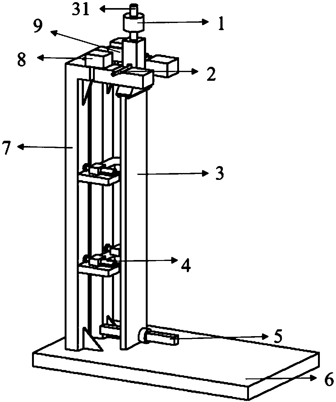
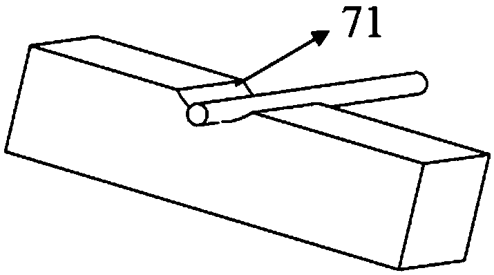
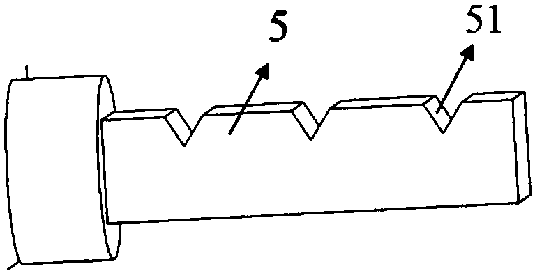
[0050]The base 6 placed horizontally, the support 7 perpendicular to the base 6 and fixedly connected thereto, the gravity compound pendulum 3, the center of mass of the gravity compound pendulum 3 passing through the compound pendulum 3 and the two ends resting on the rotating shaft support 71 at the top of the support 7 Revolving shaft 2, the two upper and lower differentials are arranged on the support 7 for measuring the horizontal swing displacement of the gravity compound pendulum 3. The macro measuring sensor 4, the counterweight 1 that can move up and down along the rod portion 31 at the top of the gravity compound pendulum 3, and the two respectively Corresponding to the calibration rod 5 ...


PUM


Abstract

The invention discloses a gravity compound pendulum-based micro force measuring device and a measuring method. In the device, a rotating shaft passes through the gravity compound pendulum and is put on a support, the compound pendulum swings an angle under effects of micro-thrust, low friction exists between the shaft and the pendulum, and thus, the micro-thrust can be sensed; the horizontal microdisplacement of the compound pendulum is measured through micro-distance sensors which are arranged in a vertical differential mode, the swinging angle is indirectly measured, and further through a moment balance relationship, the size of the micro-thrust is inversely deduced. The measuring principle and the method are simple and feasible and can reach the precision of a micro newton level; a clump weight arranged at the top end of the gravity compound pendulum can move vertically, the gravity center and the inertia of the compound pendulum are adjusted, the micro-thrust sensitivity is increased, and the influences of external vibration are reduced; the horizontal displacement of the compound pendulum is measured in a differential mode, and errors brought by environment vibration, toolingand measuring devices can be eliminated; electromagnetic damping can reduce oscillation of the compound pendulum, and influences of a disturbance torque are reduced; and besides, calibration on the micro-thrust can be directly completed through a weight calibration mode, and the operation is simple and convenient.

Description

technical field [0001] The invention relates to the field of micro-force measurement, in particular to an ultra-high-precision micro-thrust measurement device and a measurement method based on a gravity compound pendulum. Background technique [0002] With the development of science and technology, the application of experimental instruments for micro-new force measurement is more and more extensive. In the mechanical performance analysis of aerospace micro-force control, molecular biology, micro-nano manufacturing and other systems, micro-force measurement It has become a key technical link, especially in the field of aerospace, the design and detection of tiny control force requires higher measurement accuracy of the micro force value, and often needs to reach the micro-new level of precision. [0003] However, the existing force value transmission system in my country (JJG2045-1990 "Force Value (≤1MN) Measurement and Verification System") has not yet established a measure...

Claims


Application Information

Patent Timeline
Patent Type & Authority Applications(China)
IPC IPC(8): G01L1/08
CPCG01L1/08
Inventor 康国华乔思元金晨迪刘奇弦
Owner NANJING UNIV OF AERONAUTICS & ASTRONAUTICS
Learn More