
Touch panel and display module

A touch panel and display module technology, applied in character and pattern recognition, instruments, acquisition/organization of fingerprints/palmprints, etc., to reduce production costs, improve yield, and improve display quality

Active Publication Date: 2018-12-11
BOE TECH GRP CO LTD +1
View PDF9 Cites 8 Cited by
  • Summary
  • Abstract
  • Description
  • Claims
  • Application Information

AI Technical Summary

Problems solved by technology

[0005] The present invention provides a touch panel and a display module, which are used to solve the problem that the peripheral wiring of the touch substrate can be seen from the display side

Method used


Image

  • Touch panel and display module
  • Touch panel and display module
  • Touch panel and display module

Examples


Embodiment Construction

[0038] The specific implementation manner of the present invention will be further described in detail below with reference to the drawings and embodiments. The following examples are used to illustrate the present invention, but are not intended to limit the scope of the present invention.

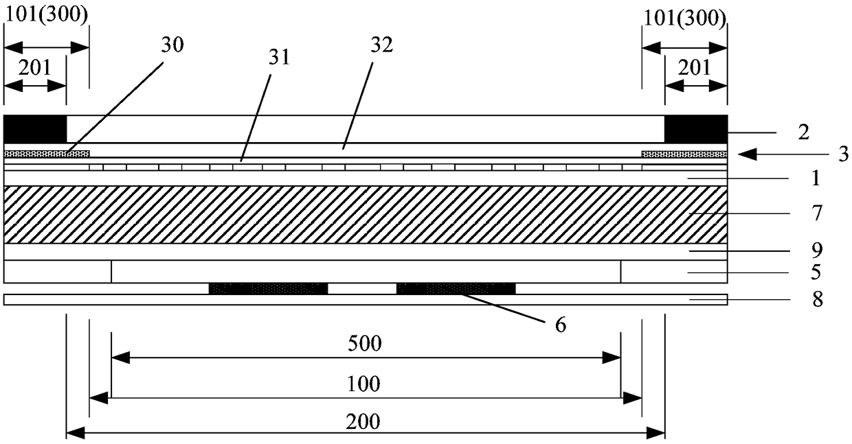
[0039] Such as image 3 As shown, a touch panel is provided in the embodiment of the present invention, which includes a touch substrate 1 and a cover plate 2 arranged oppositely, and an adhesive layer 3 is arranged between the touch substrate 1 and the cover plate 2 (the bonding layer 3 The material can be optical glue), and the adhesive layer 3 is used to fix and bond the touch control substrate 1 and the cover plate 2 . The touch substrate 1 includes a touch area 100 and a wiring area 101 located on the periphery of the touch area 100. The touch area 100 is provided with touch electrodes, and the wiring area 101 is provided with metal wires for connecting the touch electrodes and the ...


PUM


Abstract

The invention relates to the technical field of display, and discloses a touch panel and a display module. The touch panel comprises a touch substrate and a cover plate, and an adhesive layer positioned between the touch substrate and the cover plate, wherein the adhesive layer comprises a first region that is opaque to light, and light reflected by metal traces around the touch substrate is shielded by the first region that is opaque to light. In the display module, the cover plate is arranged on one side of the touch control substrate close to the display side, so that the metal traces around the touch control substrate are not visible from the display side, the display quality of the touch control display module is improved, and the appearance effect of the product is improved. Since only a part with the adhesive layer is opaque, no new patterning process is required, and the touch substrate is not affected, the yield of the product can be improved and the manufacturing cost can bereduced.

Description

technical field [0001] The invention relates to the field of display technology, in particular to a touch panel and a display module. Background technique [0002] With the continuous development and progress of touch display technology, in order to present an immersive aesthetic feeling to the audience, full-screen touch display technology has gradually become the mainstream in the world. With the rise of flexible OLED technology, full-screen touch display technology has become the main direction of research and production for mobile phone manufacturers. [0003] Schematic diagram of the mainstream structure design of the current OLED touch display module, such as figure 1 Shown: cover plate 1', first optical adhesive layer 2', polarizer 3', touch substrate 4', second optical adhesive layer 5', display panel 6', heat dissipation film 7', through different process routes Assemble together. In order to reduce the visibility of the metal traces around the touch substrate 4 ...

Claims


Application Information

Patent Timeline
IPC IPC(8): G06F3/041G06K9/00H01L27/32
CPCG06F3/0412G06V40/1306H10K59/40
Inventor 罗鸿强龚庆吴建君
Owner BOE TECH GRP CO LTD
Features
  • Generate Ideas
  • Intellectual Property
  • Life Sciences
  • Materials
  • Tech Scout
  • Unparalleled Data Quality
  • Higher Quality Content
  • 60% Fewer Hallucinations
Learn More